0 load cell wiring – Rice Lake Coil Scale RoughDeck CS User Manual
Page 9
Load Cell Wiring
19
3.0
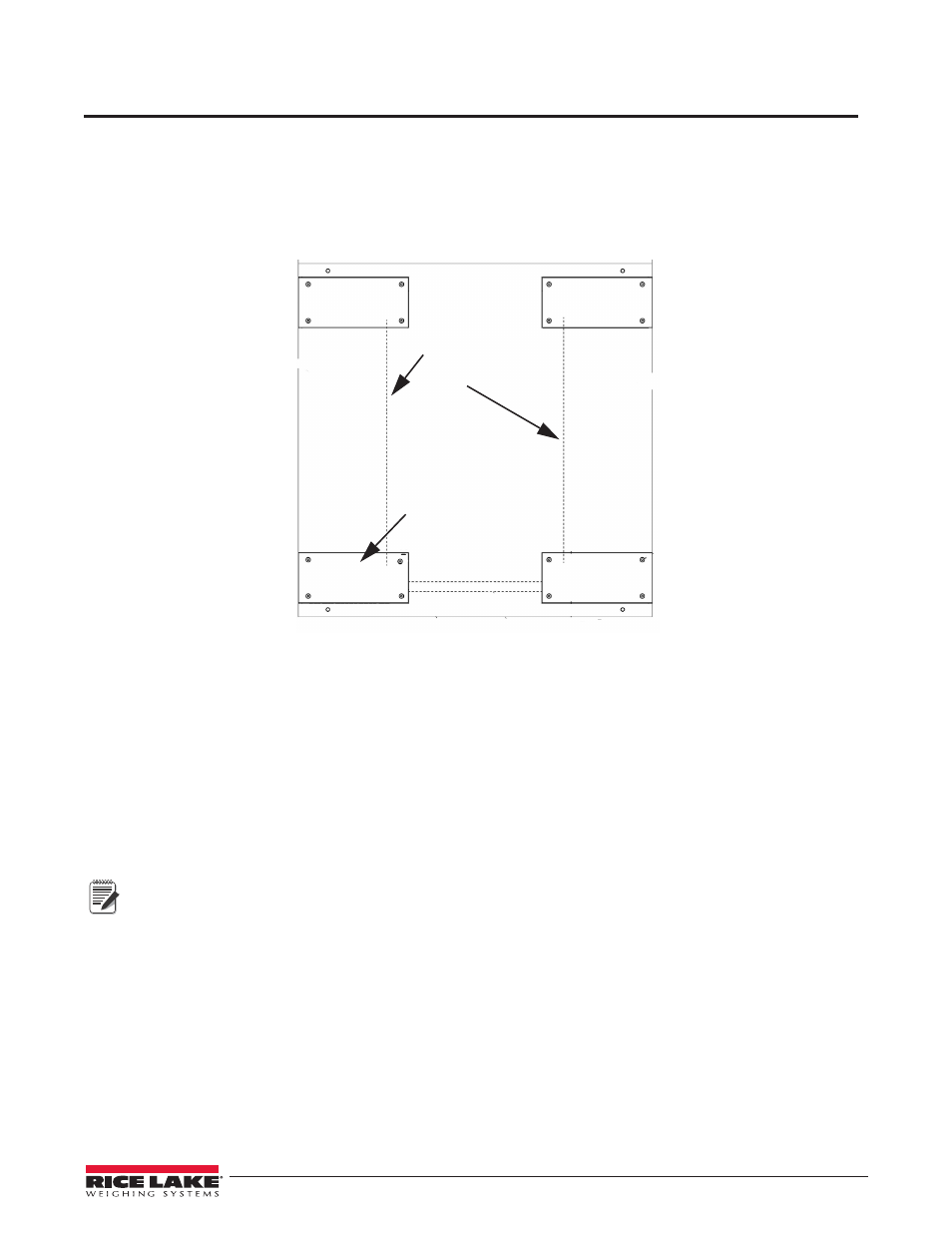
Load Cell Wiring
Before the weigh module wiring can be completed, all load cell cables have to be routed through the conduit
beginning at the load cell outlet. Use the following steps to route load cell cables through conduit to the J-box:
1. Before routing load cell cables, mark each load cell cable at the end to help identify each load cell.
2. Working from the J-box corner, insert a fish tape or similar tool and pull each load cell cable through the
rigid conduit until all excess cable is taken in.
1
2
4
3
J-box corner
Pocket 1 Conduit
Pocket 2 Conduit
Pocket 3 Conduit
Pocket 2 Conduit
Figure 3-1. J-box location
3. Wire each load cell to the J-box terminal strip in accordance with the wiring code contained in the
Certificate of Conformance.
4. Cable should not be routed near heat sources greater than 400
°
F. Do not shorten any load cell cable. The
load cell is temperature compensated with the supplied length of cable. Cutting the cable will affect
temperature compensation. Coil and protect excess cable so it will not be mechanically damaged or sit in
water.
5. Provide a drip loop in all cables so that water or other liquids will not run directly down the cables onto
either the load cells or the junction box.
6. If conduit protection is necessary against mechanical or rodent damage to the load cell cables, use flexible
conduit and conduit adapters at the load cells.
Note
Flexible conduit and conduit adapters are an optional item and not included with the standard setup.
7. Connect cables for load cells to the summing board in the junction box according to the guide shown
below and the labels on the terminal strips of the junction box. To verify the wiring scheme, see the
certification shipped with each load cell.
8. For better performance, use positive and negative remote sense lines if the wiring running from the
junction box to the indicator is longer than 25 feet