0 installation, 1 unpacking the benchmark, 1 leveling the scale – Rice Lake BenchMark HD User Manual
Page 7: 2 connecting the load cell cable, Table 2-1. load cell wiring
Installation
3
2.0
Installation
The following sections explain the installation procedure for the Benchmark HD.
2.1
Unpacking the Benchmark
Immediately after unpacking, visually inspect the Benchmark HD to ensure that the unit is undamaged. The
shipping carton should contain the bench scale and this manual. If the scale was damaged in shipment, notify Rice
Lake Weighing Systems and the shipper immediately.
2.1.1
Leveling the Scale
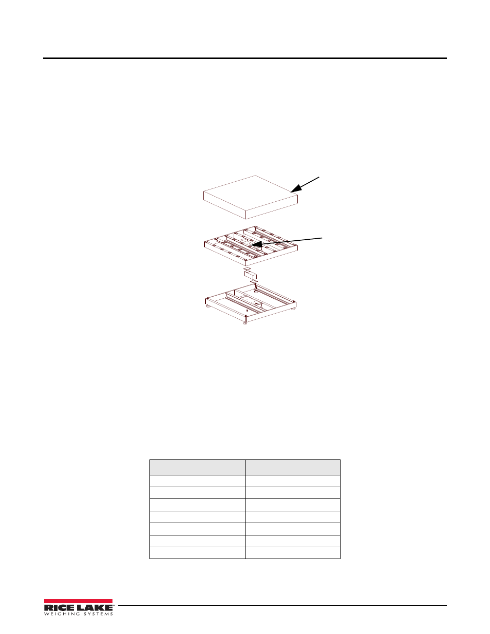
Place the scale in the desired location. Lift off the deck cover and locate the bubble level (see Figure 2-1).
Figure 2-1. Top Plate Removed Showing Bubble Level Location
Adjust the four corner feet until the scale is level and all feet contact the support surface, so that the scale does not
rock. Lock the jam nuts on the feet when the final level is correct.
2.2
Connecting the Load Cell Cable
The Benchmark HD comes with a standard 10 feet of color-coded load cell cable. Do not cut this cable. The load
cell is temperature compensated for an exact length of 10 feet.
See your indicator manual to determine the proper load cell cable input connectors. Use the following color codes
to wire the load cell cable. Once complete, install the top cover for the bench scale back onto the scale.
6-Wire Color Code
Function
Red
+ Signal
White
- Signal
Green
+ Excitation
Grey
- Excitation
Blue
+ Sense
Brown
- Sense
Yellow Shield
Table 2-1. Load Cell Wiring
Benchmark HD Deck Cover
Bubble Level Location