Rice Lake 920i Serial Expansion Card User Manual
Serial expansion card installation instructions
December 2010
69088
Serial Expansion Card Installation Instructions
PN 67604
Use the following procedure to install serial expansion
cards in
720i
,
820i
, and
920i
indicators:
1. Disconnect indicator from power source.
Disconnect power before removing
indicator backplate.
2. Place indicator face-down on an antistatic
work mat. Remove screws that hold the
backplate to the enclosure body.
Use a wrist strap to ground yourself and
protect components from electrostatic
discharge (ESD) when working inside the
indicator enclosure.
3. Carefully align the large option card
connector with connector J5 or J6 on the
920i
CPU board, J6 on the
820i
CPU board, or J12
on the
720i
CPU board. Press down to seat the
option card in the CPU board connector.
4. Use the screws and lock washers provided in
the option kit to secure the other end of the
option card to the threaded standoffs on the
CPU board (see Figure 1).
J6
Figure 1. Installing Option Card Onto 920i CPU Board
5. Make connections to the option card as
required. Use cable ties to secure loose cables
inside the enclosure. Once cabling is
complete, position the backplate over the
enclosure and reinstall the backplate screws.
Use the torque pattern shown in the indicator
Installation Manual to prevent distorting the
backplate gasket. Torque screws to 15 in-lb
(1.7 N-m).
6. Ensure no excess cable is left inside the
enclosure and tighten cord grips.
7. Reconnect power to the indicator.
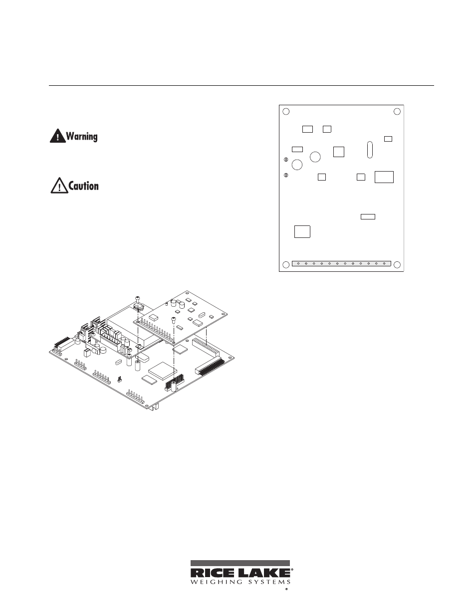
A: RS-485 RxD+
A: RS-485 TxD–
A: RS-485 TxD+
A: 20mA OUT
GND
A: RS-232 TxD
A: RS-232 RxD
B: 20mA OUT
GND
B: RS-232 TxD
B: RS-232 RxD
A: RS-485 RxD–
J2
2
3
4
5
6
7
8
9
10 11
1
12
Figure 2. Serial Expansion Card
8. Configure serial ports using the SERIAL
menu, as described in the
920i
Installation
Manual (PN 67887),
820i
Installation Manual
(PN 93018), or
720i
Installation Manual (PN
103121).
The indicator automatically recognizes all installed
option cards when the unit is powered on. No
hardware-specific configuration is required to identify
the newly-installed card to the system.
For the
920i
, a serial expansion card installed at
connector J5 on the CPU board is configured as serial
ports 5 and 6; a card installed at connector J6 is
configured as ports 7 and 8. For the
720i
and
820i
, the
serial expansion card is configured as ports 7 and 8.
To be the best by every measure