Rice Lake 920i Pulse Input Card User Manual
Pulse input card installation instructions, W arning, 920i
January 2005
69086
920i
™
Programmable HMI Indicator/Controller
Pulse Input Card Installation Instructions
PN 67603
Use the following procedure to install pulse input
cards in
920i
indicators:
1. Disconnect indicator from power source.
Disconnect power before removing
indicator backplate.
2. Place indicator face-down on an antistatic
work mat. Remove screws that hold the
backplate to the enclosure body.
Use a wrist strap to ground yourself and
protect components from electrostatic
discharge (ESD) when working inside the
indicator enclosure.
3. Carefully align the large option card
connector with connector J5 or J6 on the CPU
board. Press down to seat the option card in
the CPU board connector.
4. Use the screws and lockwashers provided in
the option kit to secure the other end of the
option card to the threaded standoffs on the
CPU board (see Figure 1).
Figure 1. Installing Option Card Onto CPU Board
5. Make connections to the option card as
required. Use cable ties to secure loose cables
i n s i d e t h e e n c l o s u r e . O n c e c a b l i n g i s
complete, position the backplate over the
enclosure and reinstall the backplate screws.
Use the torque pattern shown in Figure 2 to
prevent distorting the backplate gasket.
Torque screws to 15 in-lb (1.7 N-m).
6. Ensure no excess cable is left inside the
enclosure and tighten cord grips.
7. Reconnect power to the indicator.
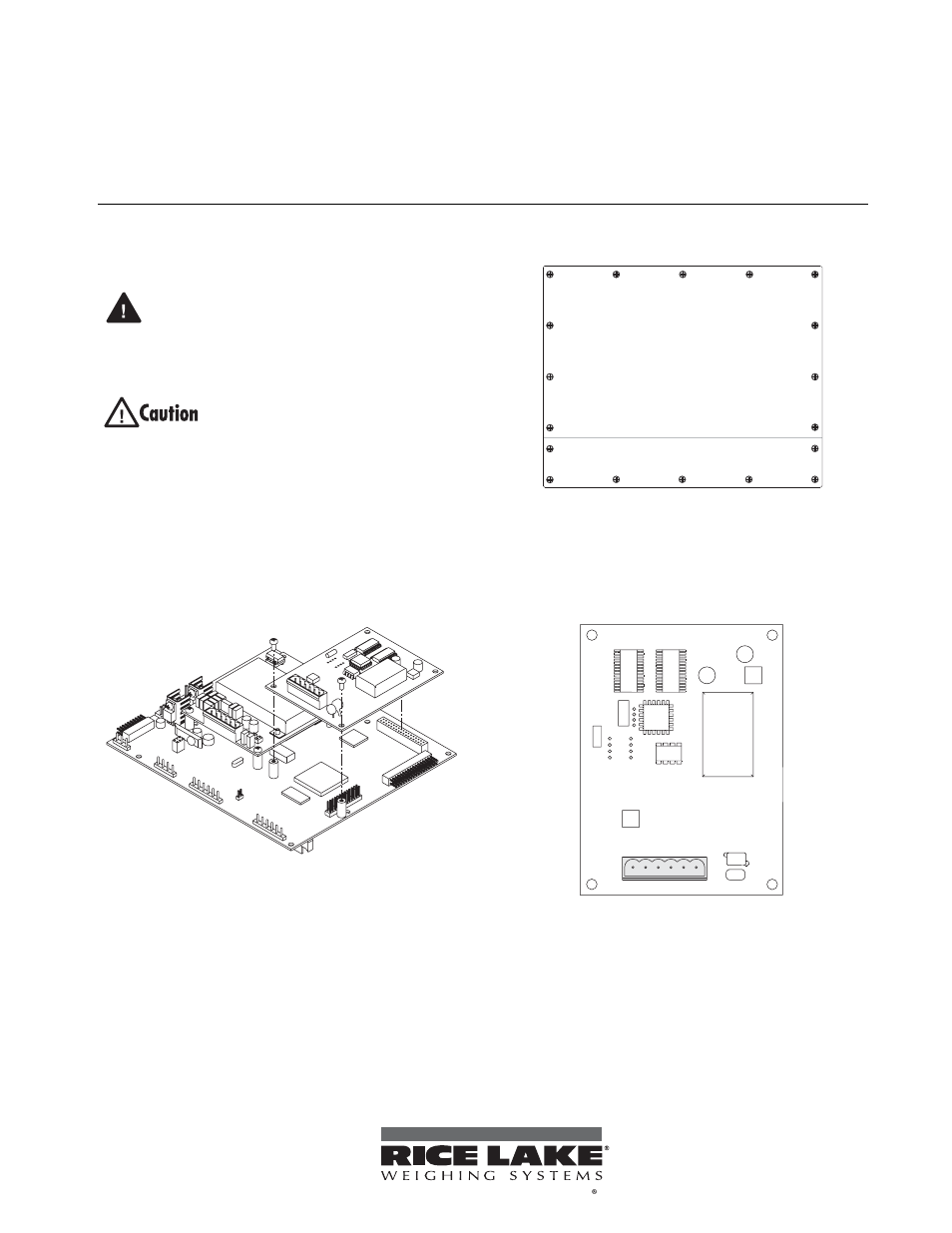
Figure 2.
920i Enclosure Backplate
The
920i
automatically recognizes all installed option
c a r d s w h e n t h e u n i t i s p o w e r e d o n . N o
hardware-specific configuration is required to identify
the newly-installed card to the system.
Figure 3. Pulse Input Card
Specifications
Sample Rate
10–4 KHz
Counting Speed
DC to 50 KHz maximum
Input
High impedance, with 1.65K
Ω pull-up
resistance. Compatible with
TTL/CMOS/switch contacts.
Logic Levels
Low: <1 V; High: >3 V, up to 12 V
W arning
J6
1
3
5
14
17
16 12
9
8
7
10
11
18
15
4
2
6
13
Torque backplate screws
to 15 in-lb (1.7 N-m)
+12V
J1
1
GND
PULSE IN
+12V
GND
PULSE IN
2
2 3 4 5 6
To be the best by every measure