Cable grounding, Power specifications, Parts kit contents – Rice Lake 920i Panel Mount User Manual
Page 4
4
920i
Panel Mount Installation Instructions
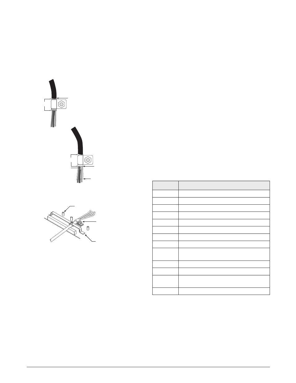
Cable Grounding
All cables routed into the panel mount enclosure
should be grounded against the indicator enclosure. Do
the following to ground shielded cables:
•
Use the lockwashers, clamps, and kep nuts
provided in the parts kit to install grounding
clamps on the enclosure studs adjacent to cord
grips.
Insulated cable
Foil (silver side out)
Grounding clamp
Shield wire (cut)
Length of foil before folding
back on cable insulation
Cut insulation here
for foil-shielded cables
Braid
Cut insulation here
for braided cables
Install lockwashers first,
against enclosure, under
grounding clamp
BRAIDED CABLE
FOIL-SHIELDED
CABLE
Figure 5. Grounding Clamp Attachment for Foil-Shielded
and Braided Cabling
Grounding clamp
Install lockwashers first,
against enclosure, under
grounding clamp
Cabling bar
Use cable ties to
bind cables to bar
Grounding clamp stud
Figure 6. Cable Installation with Grounding Clamp
•
Route cables under cabling bar (see Figure
6)
and through grounding clamps to determine
c a b l e l e n g t h s r e q u i r e d t o r e a c h c a b l e
connectors. Mark cables to remove insulation
and shield as described below:
•
For cables with foil shielding, strip insulation
and foil from the cable half an inch (13 mm)
past the grounding clamp (see Figure 5). Fold
the foil shield back on the cable where the
cable passes through the clamp. Ensure silver
(conductive) side of foil is turned outward for
contact with the grounding clamp.
•
For cables with braided shielding, strip cable
insulation and braided shield from a point just
past the grounding clamp. Strip another half
inch (13 mm) of insulation only to expose the
braid where the cable passes through the
clamp.
•
For load cell cables, cut the shield wire just
past the grounding clamp. Shield wire function
is provided by contact between the cable shield
and the grounding clamp.
•
Route stripped cables under cabling bar and
through the clamps. Ensure shields contact
grounding clamps. Tighten grounding clamp
nuts.
•
Use cable ties to secure cables to cabling bar.
Power Specifications
Line Voltages
115 or 230 VAC
Frequency
50 or 60 Hz
Maximum Power Consumption, 65W on secondary
Primary power consumption: 100W TRMS
Constant current:
1.5 A TRMS (115VAC);
1.0 A TRMS (230VAC)
See the
920i
Installation Manual for additional
specifications.
Parts Kit Contents
Table 1 lists the parts kit contents for the panel mount
version of the
920i
.
Table 1.Parts Kit Contents
PN
Description
14626
Kep nuts, 8-32NC (5)
54206
Machine screws, 6-32 x 3/8 (2)
15133
Lock washers, No. 8, Type A (5)
71522
Machine screws, 8-32NC x 1/4 (6)
82425
Machine screws, 10-32NF x 1-1/2 (9)
15631
Cable ties (4)
53075
Cable shield ground clamps (5)
94422
Capacity label (1)
15887
6-position screw terminal for load cell
connection (1)
77180
Connector, 8-position screw terminal (1)
70599
6-position screw terminals for J2 and J10 (1)
71126
4-position screw terminal for J9 and optional
keyboard connection (2)
71125
3-position screw terminal for J11 (1)