Rice Lake 920i Dual Channel A/D Card User Manual
Dual-channel a/d card installation instructions, J5 j6, W arning
December 2010
69090
920i
®
Programmable HMI Indicator/Controller
Dual-Channel A/D Card Installation Instructions
PN 68533
Use the following procedure to install dual-channel
A/D cards in
920i
indicators:
1. Disconnect indicator from power source.
W arning
Disconnect power before removing
indicator backplate.
2. Place indicator face-down on an antistatic
work mat. Remove screws that hold the
backplate to the enclosure body.
Use a wrist strap to ground yourself and
protect components from electrostatic
discharge (ESD) when working inside the
indicator enclosure.
3. Carefully align the large option card
connector with connector J5 or J6 on the CPU
board. Press down to seat the option card in
the CPU board connector.
4. Use the screws and lockwashers provided in
the option kit to secure the other end of the
option card to the threaded standoffs on the
CPU board (see Figure 1).
J5
J6
Figure 1. Installing Option Card Onto CPU Board
5. To attach cable from a load cell or junction
box to the A/D card, route the cable through
the cord grip and wrap the shield wire around
the ground stud on the enclosure. Secure
shield wire to the ground stud with the kep nut
included in the parts kit.
See the
920i
Installation Manual, PN 67887, for
more information about grounding cables.
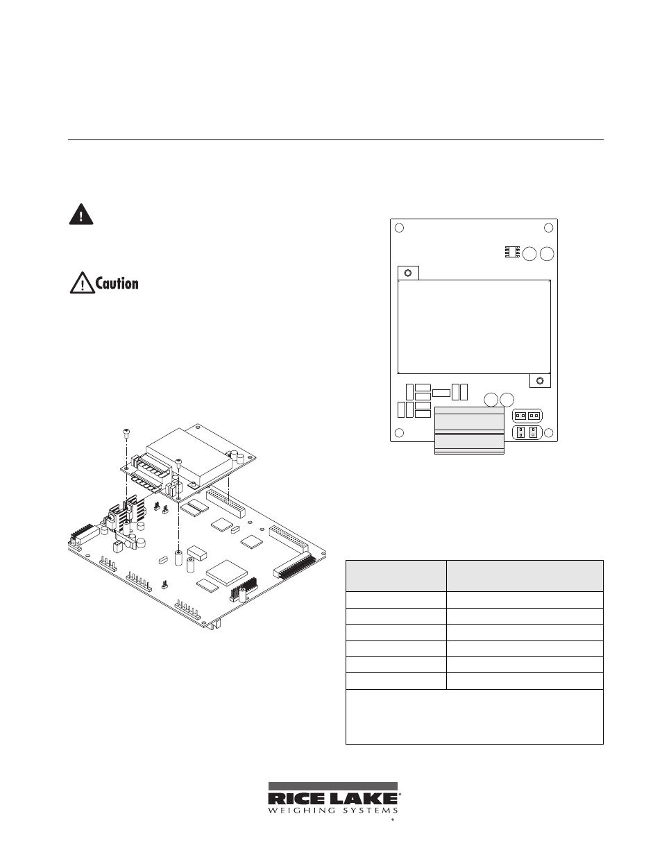
6. Next, remove connector J1 from the A/D
card. The connector plugs into a header on the
card (see Figure 2). Wire the load cell cable
from the load cell or junction box to
connector J1 as shown in Table 1.
CHANNEL 2
CHANNEL 1
SIG+
SIG–
SEN+
SEN–
EXC+
EXC–
J2
J1
JP3 JP4
JP2
JP1
CH 2
CH 1
Figure 2. Dual-Channel A/D Card
7. Remove connector J2 from the A/D card and
wire the second load cell cable from the load
cell or junction box to connector J2 as shown
in Table 1.
Table 1. A/D Card Pin Assignments
J1/J2
Connector Pin
Function
1
+SIG
2
–SIG
3
+SENSE
4
–SENSE
5
+EXC
6
–EXC
•
For 6-wire load cell connections to connector J1, remove
jumpers JP1 and JP2.
•
For 6-wire load cell connections to connector J2, remove
jumpers JP3 and JP4.
To be the best by every measure