Cable grounding, Power specifications, Parts kit contents – Rice Lake 920i Deep Enclosure User Manual
Page 2
2
920i
Deep Enclosure Installation Instructions
Deep enclosure models of the
920i
provide eight cord
grips for cabling into the indicator. The parts kit
includes cord grip plugs to prevent moisture from
entering the enclosure. Install these plugs into all cord
grips that will be not be used in your application. Use
the cable grounding instructions below for wiring into
the indicator.
Cable Grounding
Cables routed through the cord grips should be
grounded against the indicator enclosure. Do the
following to ground shielded cables:
•
Use the lockwashers, clamps, and kep nuts
provided in the parts kit to install grounding
clamps on the enclosure studs adjacent to cord
grips. Install grounding clamps only for cord grips
that will be used; do not tighten nuts.
•
Route cables through cord grips and grounding
clamps to determine cable lengths required to
reach cable connectors. Mark cables to remove
insulation and shield as described below:
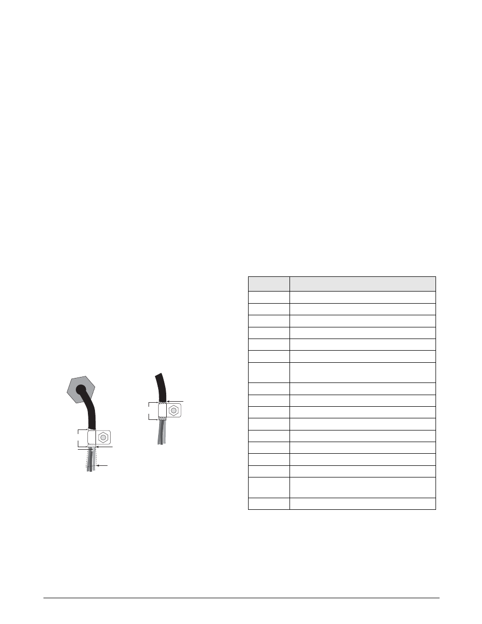
• For cables with foil shielding, strip insulation
and foil from the cable half an inch (15 mm)
past the grounding clamp (see Figure 2). Fold
the foil shield back on the cable where the cable
passes through the clamp. Ensure silver
(conductive) side of foil is turned outward for
contact with the grounding clamp.
• For cables with braided shielding, strip cable
insulation and braided shield from a point just
past the grounding clamp. Strip another half
inch (15 mm) of insulation only to expose the
braid where the cable passes through the clamp.
Figure 2. Grounding Clamp Attachment for Foil-Shielded
and Braided Cabling
•
For load cell cables, cut the shield wire just past
the grounding clamp. Shield wire function is
provided by contact between the cable shield and
the grounding clamp.
•
Route stripped cables through cord grips and
clamps. Ensure shields contact grounding clamps
as shown in Figure 2. Tighten grounding clamp
nuts.
•
Finish installation using cable ties to secure
cables inside of indicator enclosure.
Power Specifications
Line Voltages
115 or 230 VAC
Frequency
50 or 60 Hz
Maximum Power Consumption, 65W on secondary
Primary power consumption: 100W TRMS
Constant current:
1.5 A TRMS (115VAC);
1.0 A TRMS (230VAC)
Fusing
115 VAC and 230 VAC North American
2 x 3.15A TR5 subminiature fuses
Wickmann Time-Lag 19374 Series
UL Listed, CSA Certified and Approved
230 VAC European
2 x 3.15A TR5 subminiature fuses
Wickmann Time-Lag 19372 Series
UL Recognized, Semko and VDE Approved
See the
920i
Installation Manual, PN 67887, for
additional specifications.
Parts Kit Contents
Table 1 lists the parts kit contents for deep enclosure
models of the
920i
.
$PSEHSJQ
*OTVMBUFEDBCMF
'PJM TJMWFSTJEFPVU
(SPVOEJOHDMBNQ
4IJFMEXJSF DVU
-FOHUIPGGPJMCFGPSFGPMEJOH
CBDLPODBCMFJOTVMBUJPO
$VUJOTVMBUJPOIFSF
GPSGPJMTIJFMEFEDBCMFT
#SBJE
$VUJOTVMBUJPOIFSF
GPSCSBJEFEDBCMFT
/05&*OTUBMMMPDLXBTIFST
mSTU BHBJOTUFODMPTVSF
VOEFSHSPVOEJOHDMBNQ
PN
Description
14626
Kep nuts, 8-32NC (4)
14862
Machine screws, 8-32NC x 3/8 (12)
15133
Lock washers, No. 8, Type A (4)
15144
Nylon washers (2)
15631
Cable ties (4–single A/D, 6–dual A/D)
15665
Reducing glands for 1/2 NPT cord grips (2)
15887
6-position screw terminal for load cell
connection (1–single A/D, 2–dual A/D)
19538
Cord grip plugs (4–single A/D, 3–dual A/D)
30623
Fillister head screws, 8-32NC x 7/16 (2)
42149
Rubber feet for tilt stand (4)
42350
Capacity label (1–single A/D, 2–dual A/D)
53075
Cable shield ground clamps (4)
68403
Wing knobs for tilt stand (2)
70599
6-position screw terminals for J2 and J10 (2)
71125
3-position screw terminal for J11 (1)
71126
4-position screw terminal for J9 and optional
keyboard connection (2)
75062
Sealing washers (14)
Table 1. Parts Kit Contents