Rice Lake 920i Programmable HMI Indicator/Controller - 2-Card Expansion Board User Manual
Page 3
3
Wall Mount Installation (69782)
Use the following procedure to install the two-card
expansion board in the wall mount enclosure. See
Figure 3 below and Figure 4 on page 4 for locations of
option kit components.
1. Disconnect indicator from power source.
2. Open enclosure.
3. Screw eight 1/2" standoffs (PN 71452) into the
holes in the enclosure backplate.
4. Clip the six cable ties that secure the cable
assembly from the power supply to the CPU
board. Remove CPU board power supply cable
and replace with the cable in the expansion
board option kit. Connect new cable to power
input connector on CPU board.
5. Remove adhesive covering from two ribbon
cable clamps and install on door and side wall
of enclosure (see Figure 3).
6. Attach ribbon cable to connector J7 on the
CPU board. Slide the ribbon cable into the
cable clamps and extend cable to full length.
(Ribbon cable attaches to right side of installed
expansion board. See Figure 4 on page 4).
7. Mount two-card expansion board on installed
standoffs. (Ensure that ribbon cable is routed
under the expansion board and extends to the
right of the board.) Use four 1/4" screws (PN
14822) to secure board to standoffs.
8. Install four 1/2" standoffs (PN 71452) onto the
expansion board to support option cards.
9. Attach ribbon cable to connector J3 on the
expansion board.
10. Attach power cable to connector J4 on the
expansion board.
11. Set the slot/location jumper to the 3–4 position
(see Figure 1 on page 1).
12. Install option cards onto expansion board (see
page 4). Use the supplied cable ties to secure
all loose cables inside the enclosure.
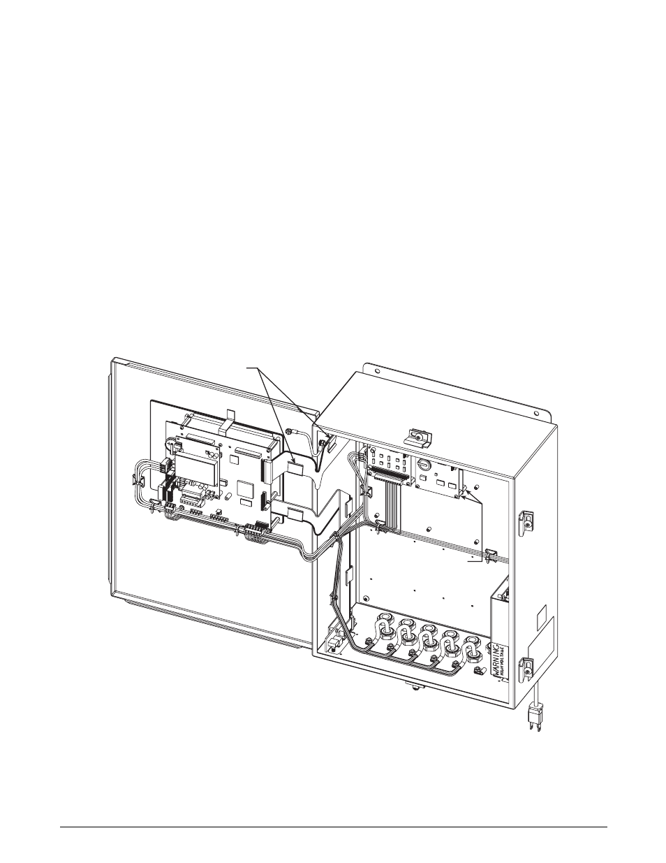
1/2" STANDOFFS (12)
RIBBON CABLE
CLAMPS
Figure 3. Two-Card Expansion Board Installed in Wall Mount Enclosure, Isometric View