Analog output calibration – Rice Lake 520 Analog Output Card Installation User Manual
Page 2
Rice Lake Weighing Systems
Analog Output Calibration
The following calibration procedure requires a
multimeter to measure voltage or current output from
the analog output module.
Note
The analog output must be calibrated after the
indicator itself has been configured and
calibrated.
1. Enter setup mode and go to the ALGOUT menu
(see Figure 4):
• Set
OFFSET
to 0% for 0–10 V output; set to
20% for 4–20 mA output
• Set mode select jumper on the analog output
board to "V" for 0-10 V output, or "I" for
4-20mA output
• Set MIN to lowest weight value to be tracked
by the analog output
• Set MAX to highest weight value to be tracked
by the analog output
2. Connect multimeter to connector J1 on the analog
output board:
• For voltage output, connect voltmeter leads to
pin 3 and 4.
• For current output, connect ammeter leads to
pins 1 and 2.
3. Adjust zero calibration: Scroll to the TWZERO
parameter. Press
to view zero value, then check
voltage or current reading on multimeter. Press and
hold or
to adjust the zero value up or down.
4. Adjust span calibration: Scroll to the TWSPAN
parameter. Press
to view span value, then check
voltage or current reading on multimeter. Press and
hold
or
to adjust the span value up or down.
5. Final zero calibration: Return to the TWZERO
parameter and verify that the zero calibration has
not drifted. Press and hold
or
to re-adjust the
zero value as required.
6. Return to normal mode. Analog output function
can be verified using test weights.
See the 520 Installation Manual, PN 68973, for more
configuration information.
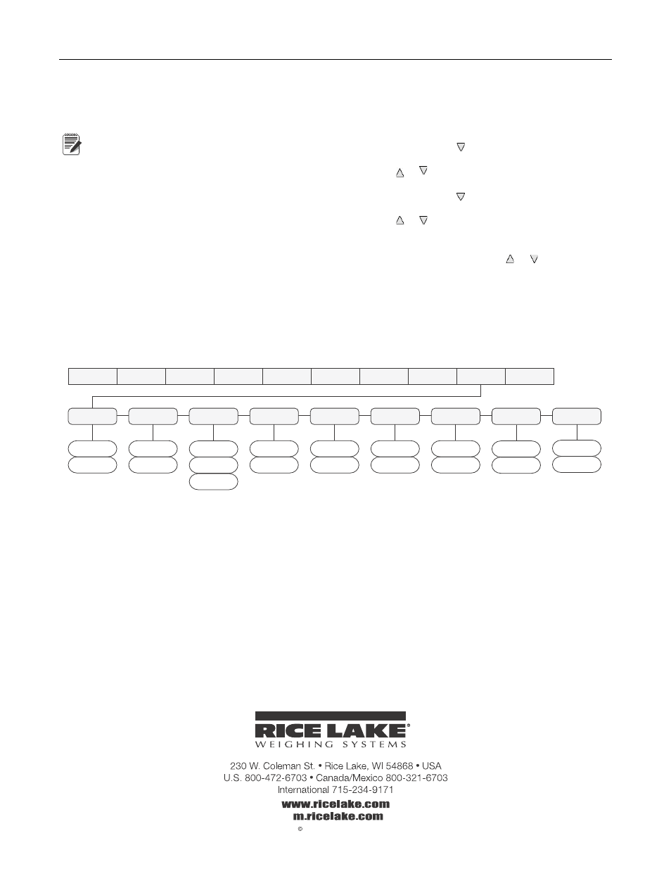
XXXXXXX
ALGOUT
XXXXXXX
DIG IN
SETPTS
PROGRM
XXXXXXX
PFORMT
SERIAL
CALIBR
CONFIG
XXXXXXX
FORMAT
OFF
ON
MINNEG
10000
number
MAX
SOURCE1
GROSS
NET
ERRACT
FULLSC
HOLD
ZEROSC
XXXXXXX
VERS
TWZERO
71
number
0%
20%
OFFSET
000000
number
MIN
OFF
ON
MAXNEG
15171
number
TWSPAN
Figure 4. Analog Output Menu
Specifications
Resolution
16-bit, monotonicity over temperature
Linearity
±0.03% of full scale input
Current Output
0–20 mA or 4–20 mA (20% offset)
Maximum Load Resistance
840 Ω
Power Consumption
3.9W (max. load @ 20 mA)
Voltage Output
0–10 VDC
Minimum Load Resistance
1.2 KΩ
Power Consumption
3.9W (max. load @ 10 VDC)
Input Protection
Short circuit protection, 300W transient voltage suppression
Protection for ESD, EFT (electrical fast transients), tertiary lightning, and system-generated
transients per IEC 60001-4-2, 60001-4-4, and 60001-4-5; European Standards EN50082
and EN61000-4