Cable connections and installation – Rice Lake 320IS Intrinsically-Safe Digital Weight Indicator - IS-6V Battery Pack Instruction Sheet User Manual
Page 2
2
IS-6V Battery Pack Installation Instruction Sheet
Cable Connections and Installation
The following section contains information on cable connections and installation for the
IS–6V Battery Pack
to a
320IS/320IS Plus
indicator.
NOTE: Intrinsically safe cables are specified by control drawing. All cables must meet the appropriate internal
inductance and capacitance according to the control drawing. Cable lengths are based on group classifications.
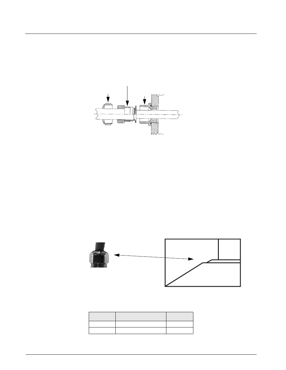
Figure 2. Cord Grip
Use the following procedure for connecting braided power cable:
1. Carefully remove 3" of insulation and 2 1/2" of braid from cable.
2. Remove domed cap and reducing gland from cord grip and place them on the cable. See Figure 2 above.
3. Remove domed cap and reducing gland from the parts kit. DO NOT confuse these with the parts
removed from the cord grip.
4. Transfer the metal piece of the reducing gland removed from the cord grip to the reducing gland from the
indicator parts kit.
5. Place the domed cap and reducing gland you removed from the indicator parts kit to the cable.
6. Install cable through cord grip stem, leaving braid outside of cord grip.
7. Lower reducing gland to edge of insulation and wrap braid over metal part of reducing gland.
8. Insert cable and reducing gland into cord grip stem.
9. Lower domed cap onto cord grip and tighten until a small swelling of the rubber between the domed cap
and the cable builds. See Figure 3 below.
Figure 3. Proper Cord Grip Compression
10. Wire cable to connector CN1. See Section 2.3.1 on page 6 of the
320IS
manual.
Table 1. DC Power Supply Connections
CN 1 Pin
Function
Color
1
+Voltage (5.8 – 7.9)
Green
2
Ground (V–, Common)
Brown
Stem
Reducing Gland
Domed Cap