Purpose, Example, Specifications – Rice Lake 320IS Intrinsically-Safe Digital Weight Indicator - Timer Relay Instruction Sheet User Manual
Page 2
2
320IS Timer Relay Option Instructions
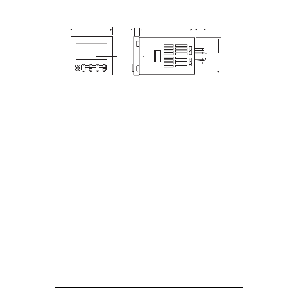
Figure 3-1. Relay Dimensions
Purpose
The timer relay is a latching device that allows a continuous (free running) setpoint output to be held until a start
input is received.
Example
Setpoint 1 is set to a value of 1000, trip lower. The relay of the I/O module is active until 1000 is achieved. The
timer relay becomes active with a start input from an external source. Once the setpoint value is achieved the timer
will deactivate and, even though the I/O relay wired to it will become active again below the setpoint value, the
timer relay will remain deactivated until the next start command.
Specifications
Electrical Ratings
Power Consumption:
100...240VAC
24V AC/12...24VDC
4.3 VA
3.4 VA/1.7 W
Inputs:
Input signals: Start, reset
Input method: No-voltage input via
NPN transistor or switching of
contacts
Start, reset, gate: Minimum input
signal width - 1 or 20 ms
(selectable)
Power reset: Minimum
power-opening time - 0.5s (Except
for A-3, B-1, and F-mode)
Mechanical
Display:
7-segment, negative transmissive
LCD; Present value (red, 8 mm
high characters); Set value (green,
4 mm high characters)
Digits:
4
digits
Enclosure
Weight:
Approx. 100 g
Enclosure Ratings:
Panel surface - IP66 and NEMA
Type 4 (indoors)*
Approval Standards
UL508, CSAS C22.2 NO.14
Conforms to EN61010-1/
IEC61010-1
(Pollution degree 2/over voltage
category II)
Conforms to VDEO106/P100
(Finger Protection), conforms to
NEMA output rating (N/F)
44.8 . 44.8
63.7
6
14.3
48 . 48