Origin Live Enterprise C User Manual
Page 4
Page 4
Re-setting the dual points if original settings are lost
Place the arm in the arm clip
to ensure the
arm is roughly level along its length.
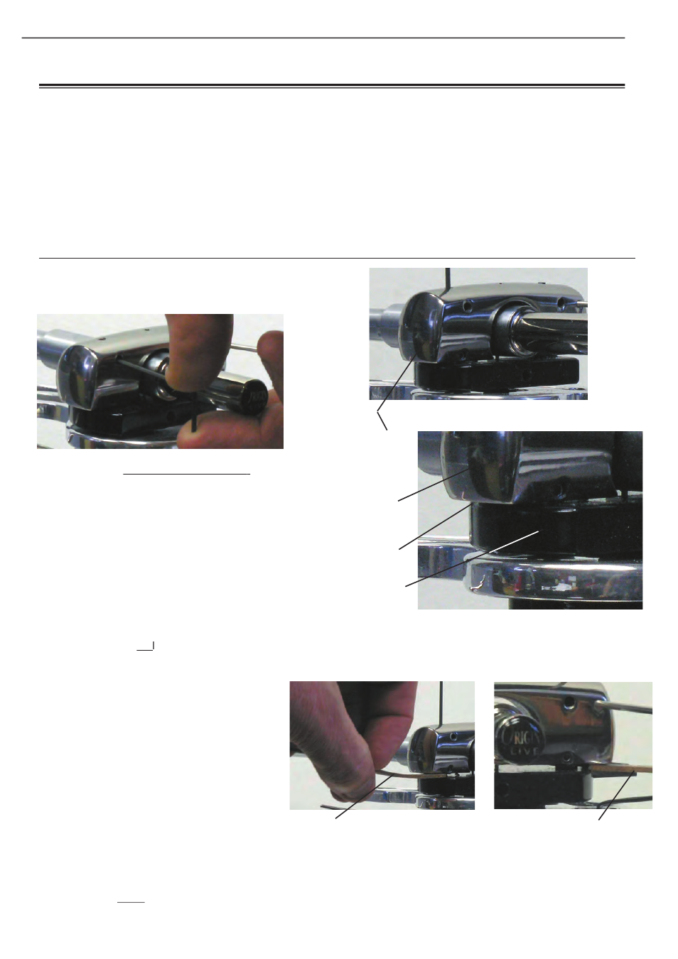
Now turn the 2 azimuth pivot adjuster screws
anti-clockwise to lower the yoke till it touches
the turret plate and then unwind the screw a
further turn.
Next wind in each adjuster screw (clockwise)
to the stage where it just
just starts to lift the
just
just
yoke off the turrret plate. Th is is what will be
referred to as the “ground datum position” .
NOTE: Th ere are thin protrusions on the
underside of the yoke under the pivot screw
positions - Th e underside of these protrusions
are considered to be the underside of the
yoke.
Th ere are two methods of achieving this
“ground datum position”. Th e fi rst is to push
down on the yoke hard with the thumb of
one hand. At the same time wind a pivot
adjuster screw clockwise. At fi rst the screw
will be relatively free but when it meets the
jewelled cup and starts lifting the yoke against
the force of your thumb the resistance to
turning will increase signifi cantly. Th e point
where resistance starts is the ground datum.
Ensure that the 2 Azimuth clamping screws
Azimuth clamping screws are
slack by winding them anti-clockwise approx 1
turn
Enlargement
photo of “gap”
area
YOKE
NO GAP BETWEEN
YOKE & TURRENT
PLATE
TURRET PLATE
1 TURN ON THE AZIMUTH ADJUSTER
SCREW = 0.5MM INCREASE RISE OF YOKE
PHOTO 4
CORK STRIP INSERTED ON LEFT
SIDE IN 1.5MM GAP BETWEEN YOKE
AND TURRET PLATE
SUMMARY OF PROCEEDURE Th e headshell is
factory set to be perfectly parrallel to the bottom face of the
yoke in terms of rotation (azimuth). We therefore use the
bottom face of the Yoke as one key reference - i.e. if the
yoke is level then we know the headshell azimuth is correct
(azimuth is the rotation of the headshell relative to vertical).
Th e aim of the adjustment described below is to end up
with the bottom face of the yoke level and 1.5mm above
the top surface of the semi-circular yoke plate
directly
underneath it. Note: Th e yoke plate is perfectly level.
A summary of the proceedure described below is fi rstly to
lower the yoke so that its bottom face (protrusions) nearly
rests on the turret plate. Th is gives a rough reference point
to start from. Next, raise the yoke exactly 1.5 mm by
turning the azimuth adjuster screws 3 turns. Check yoke is
level and if not then fi ne adjust it, using the cork strip till
exactly level on both sides of the yoke.
DETAILS FOR SETTING UP BEARING POINTS
CORK STRIP INSERTED ON
RIGHT SIDE IN 1.5MM GAP
BETWEEN YOKE AND TURRET
PLATE
PHOTO 5