Dp connectors (dp0/dp1), Dvi connector (dvi-i), Omniclient – user’s guide (v1.01) – Kontron OmniClient User Manual
Page 47
OmniClient – User’s Guide (V1.01)
46
www.kontron.com
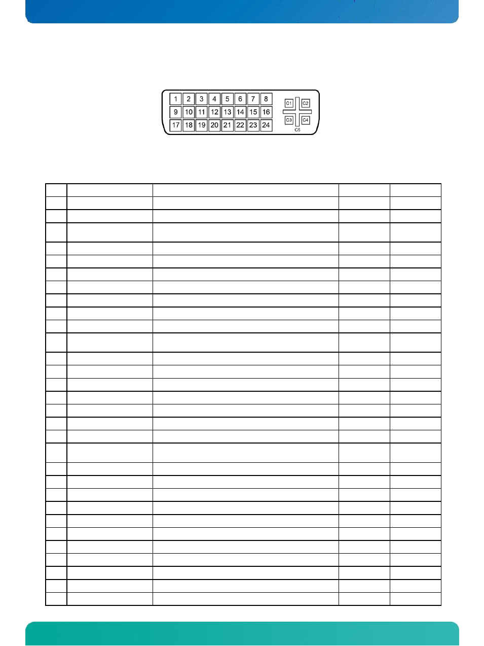
12.3. DVI Connector (DVI-I)
The DVI-I connector support DVI Digital output and DVI analog output.
Figure 2. DVI-I Female socket, front view
Table 12: Signal Description
– DVI-I connector
Pin Signal
Description
Type
Pull U/D
1
TMDS Data 2-
Digital Red
– (Link 1)
LVDS OUT
2
TMDS Data 2+
Digital Red + (Link 1)
LVDS OUT
3
TMDS Data 2/4
Shield
PWR
4
NC
NC
5
NC
NC
6
DDC Clock
DDC Clock
IO
2K2
7
DDC Data
DDC Data
IO
2K2
8
NC
NC
9
TMDS Data 1-
Digital Green
– (Link 1)
LVDS OUT
10
TMDS Data 1+
Digital Green + (Link 1)
LVDS OUT
11
TMDS Data 1/3
Shield
PWR
12
NC
NC
13
NC
NC
14
+5V
Power for monitor when in standby
PWR
15
GND
PWR
16
Hot Plug Detect
Hot Plug Detect
I
17
TMDS Data 0-
Digital Blue
– (Link 1) / Digital sync
LVDS OUT
18
TMDS Data 0+
Digital Blue + (Link 1) / Digital sync
LVDS OUT
19
TMDS Data 0/5
Shield
PWR
20
NC
NC
21
NC
NC
22
TMDS Clock Shield
PWR
23
TMDS Clock+
Digital clock + (Link 1)
LVDS OUT
24
TMDS Clock-
Digital clock - (Link 1)
LVDS OUT
C1 ANALOG RED
Analog output carrying the red color signal
O
/75R
C2 ANALOG GREEN
Analog output carrying the green color signal
O
/75R
C3 ANALOG BLUE
Analog output carrying the blue color signal
O
/75R
C4 ANALOG HSYNC
CRT horizontal synchronization output.
O
C5 ANALOG GND
Ground reference for RED, GREEN, and BLUE
PWR
C6 ANALOG GND
Ground reference for RED, GREEN, and BLUE
PWR