2 introduction, 1 product description, 2 naming clarification – Kontron COMe-cDC2 User Manual
Page 8: 3 understanding com express® functionality, Introduction, Product description, Naming clarification, Understanding com express® functionality, Come-cdc2 / introduction
COMe-cDC2 / Introduction
2 Introduction
2.1
Product Description
The COMe-cDC2 brings latest 45 nm performance generations of Intel® Atom™ N270 processor with 1.6 GHz and the
Intel® 945GSE and ICH7M chipset to a compact 95 x 95 mm module.
Kontron’s new high-efficient power-off state S5 Eco enables ACPI features and lowest power-consumption in soft-off
state – less than 1 mA. Compared to the regular S5 state this means a reduction by at least factor 200! Battery uptime
therefore goes up dramatically.
Like all COM Express® compact modules, it is compatible to the COM Express® basic. Therefore, upgrading existing carrier
boards originally designed for COM Express® basic gets easy and minimizes redesign efforts.
2.2
Naming clarification
COM Express® defines a Computer-On-Module, or COM, with all components necessary for a bootable host computer,
packaged as a super component.
» COMe-bXX# modules are Kontron's COM Express® modules in basic form factor (125mm x 95mm), formerly known
as ETXexpress®
» COMe-cXX# modules are Kontron's COM Express® modules in compact form factor (95mm x 95mm), formerly known
as microETXexpress®
» COMe-mXX# modules are Kontron's COM Express® modules in mini form factor (55mm x 84mm), formerly known as
nanoETXexpress
The product names for Kontron COM Express® Computer-on-Modules consist of a short form of the industry standard
(
COMe-), the form factor (b=basic, c=compact, m=mini), the capital letters for the CPU and Chipset Codenames (XX) and
the pin-out type (
#) followed by the CPU Name.
2.3
Understanding COM Express® Functionality
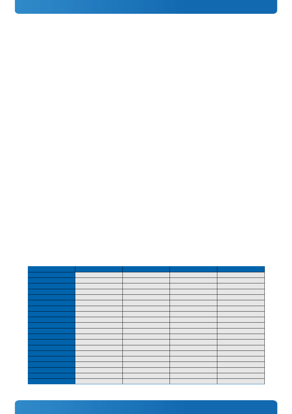
All Kontron COM Express® basic and compact modules contain two 220pin connectors; each of it has two rows called Row
A & B on primary connector and Row C & D on secondary connector. COM Express® Computer-on-modules feature the
following maximum amount of interfaces according to the PICMG module Pin-out type:
Feature
Pin-Out Type 1
Pin-Out Type 10
Pin-Out Type 2
Pin-Out Type 6
HD Audio
1x
1x
1x
1x
Gbit Ethernet
1x
1x
1x
1x
Serial ATA
4x
4x
4x
4x
Parallel ATA
-
-
1x
-
PCI
-
-
1x
-
PCI Express x1
6x
6x
6x
8x
PCI Express x16 (PEG)
-
-
1x
1x
USB Client
1x
1x
-
-
USB 2.0
8x
8x
8x
8x
USB 3.0
-
2x
-
4x
VGA
1x
-
1x
1x
LVDS
Dual Channel
Single Channel
Dual Channel
Dual Channel
DP++ (SDVO/DP/HDMI/DVI)
1x optional
1x
3x shared with PEG
3x
LPC
1x
1x
1x
1x
External SMB
1x
1x
1x
1x
External I2C
1x
1x
1x
1x
GPIO
8x
8x
8x
8x
SDIO
1x optional
1x optional
-
-
UART (2-wire COM)
-
2x
-
2x
FAN PWM out
-
1x
-
1x
8