10 slot 3 connector j19, Slot 3 connector j19, Slot 3 connector j19 pinout – Kontron COMe Eval Carrier QorIQ User Manual
Page 21
www.kontron.com
21
Quick Start Guide
COME-QEC-1
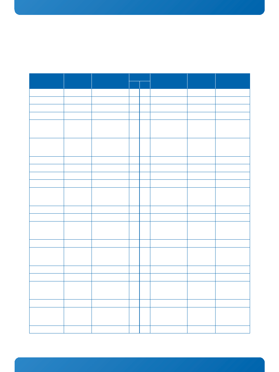
5.2.10 SLOT 3 Connector J19
Slot 3 and its dedicated sideband signal connector J25 provide the possibility to verify the SGMII and XAUI capability of the
mounted COM Express® module. The main connector J19 provides up to four GigEthernet SGMII interfaces or one XAUI interface
whereas the sideband connector adds several sideband signals which are necessary for operation of the S0010 SGMII-Adapter
Card or the S0011 XAUI-Adapter Card or to assist in designing special custom adapter cards.
Table 8: SLOT 3 Connector J19 Pinout
COMMENT
COM EXPRESS
CONNECTION
SIGNAL
PIN SIDE
SIGNAL
COM EXPRESS
CONNECTION
COMMENT
B
A
12V power supply
V_12V+
1
1
NC
Not connected
12V power supply
V_12V+
2
2
V_12V+
12V power supply
12V power supply
V_12V+
3
3
V_12V+
12V power supply
Ground
GND
4
4
GND
Ground
SMBus clock from
COME module
(refer to Table 20)
buffered signal
of SMB_CK
I2C_SMB_SCL
5
5
NC
Not connected
SMBus data from/
to COME module
(refer to Table 20)
buffered signal
of SMB_DAT
I2C_SMB_SDA
6
6
NC
Not connected
Ground
GND
7
7
NC
Not connected
3.3V power supply
V_3V3
8
8
NC
Not connected
Not connected
NC
9
9
V_3V3
3.3V power supply
3.3V power supply
V_3V3
10
10 V_3V3
3.3V power supply
Wake1# signal to
COME module
WAKE1#
WAKE[1]#
11
11 RESET_PCIE_SLOT3#
PCIe Reset from
Carrier glue logic,
low active
Not connected
NC
12
12 GND
Ground
Ground
GND
13
13 NC
Not connected
SerDes transmit-
ter differential
pair, Lane 0
SERDES_TX10+ SLOT3_SD_TX[0]+
14
14 NC
Not connected
SERDES_TX10- SLOT3_SD_TX[0]-
15
15 GND
Ground
Ground
GND
16
16 SLOT3_SD_RX[0]+
SERDES_RX10+ SerDes receiver
differential pair,
Lane 0
Not connected
NC
17
17 SLOT3_SD_RX[0]-
SERDES_RX10-
Ground
GND
18
18 GND
Ground
SerDes transmit-
ter differential
pair, Lane 1
SERDES_TX11+ SLOT3_SD_TX[1]+
19
19 NC
Not connected
SERDES_TX11- SLOT3_SD_TX[1]-
20
20 GND
Ground
Ground
GND
21
21 SLOT3_SD_RX[1]+
SERDES_RX11+ SerDes receiver
differential pair,
Lane 1
Ground
GND
22
22 SLOT3_SD_RX[1]-
SERDES_RX11-