9 slot 2 connector j18, Slot 2 connector j18, Slot 2 connector j18 pinout – Kontron COMe Eval Carrier QorIQ User Manual
Page 19
www.kontron.com
19
Quick Start Guide
COME-QEC-1
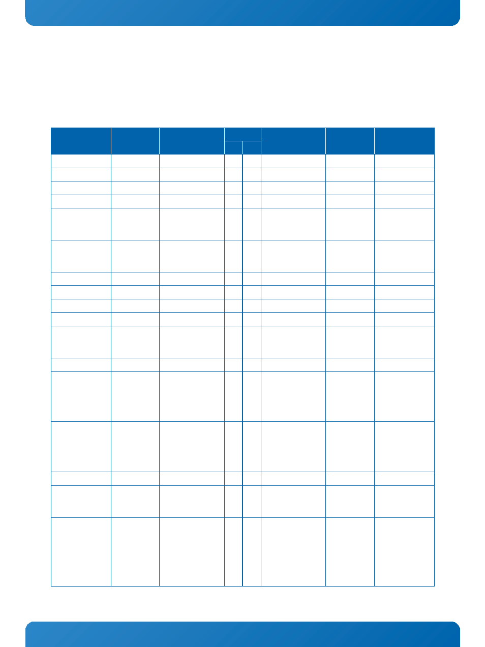
5.2.9 SLOT 2 Connector J18
Slot 2 and its dedicated sideband signal connector J24 provide the possibility to verify the PCIe and sRIO capability of the
mounted COM Express® module. The main connector J18 provides the x4 interface connectivity whereas the sideband connec-
tor adds several sideband signals which are necessary for operation of the S0012 SRIO-Adapter Card or to assist in designing
special custom adapter cards.
Table 7: SLOT 2 Connector J18 Pinout
COMMENT
COM EXPRESS
CONNECTION
SIGNAL
PIN SIDE
SIGNAL
COM EXPRESS
CONNECTION
COMMENT
B
A
12V power supply
V_12V+
1
1
PRSNT1#
Grounded
12V power supply
V_12V+
2
2
V_12V+
12V power supply
12V power supply
V_12V+
3
3
V_12V+
12V power supply
Ground
GND
4
4
GND
Ground
SMBus clock from
COME module
(refer to Table 20)
buffered signal
of SMB_CK
I2C_SMB_SCL
5
5
NC
Not connected
SMBus data from/
to COME module
(refer to Table 20)
buffered signal
of SMB_DAT
I2C_SMB_SDA
6
6
NC
Not connected
Ground
GND
7
7
NC
Not connected
3.3V power supply
V_3V3
8
8
NC
Not connected
Not connected
NC
9
9
V_3V3
3.3V power supply
3.3V power supply
V_3V3
10
10 V_3V3
3.3V power supply
Wake0# signal to
COME module
WAKE0#
WAKE[0]#
11
11 RESET_PCIE_SLOT2#
PCIe Reset from
Carrier glue logic,
low active
Not connected
NC
12
12 GND
Ground
Ground
GND
13
13 CLK_PCIE_SLOT2+
buffered signal
of
SERDES_CK_RE
F+
100MHz PCIe refer-
ence clock, differ-
ential pair
SerDes transmit-
ter differential
pair, Lane 0
SERDES_TX4+ SLOT2_SD_TX[0]+
14
14 CLK_PCIE_SLOT2-
buffered signal
of
SERDES_CK_RE
F-
SERDES_TX4-
SLOT2_SD_TX[0]-
15
15 GND
Ground
Ground
GND
16
16 SLOT2_SD_RX[0]+
SERDES_RX4+ SerDes receiver
differential pair,
Lane 0
EXCD0_CPPE# sig-
nal to COME mod-
ule, PRSNT# card
detect signal to
carrier glue logic,
8k2 PU on carrier
to V_3V3_STDBY
EXCD1_CPPE#
EXCD1_CPPE#
17
17 SLOT2_SD_RX[0]-
SERDES_RX4-