19 switch led assignment - 21, At8904m hardware description – Kontron AT8904 User Manual
Page 55
AT8904M
Hardware Description
Page 3 - 21
AT8904M User Guide
The STAT/ACT LED number on the front plate indicates the logical ATCA slot (not the channel
number) of the connection. LED 1 for the base interface is the combined status/activity LED for
both ShMC links. If any of the two ShMC links is up, the LED is lit. If any of the links is active,
the LED blinks. LED 1 is not used for the fabric interface.
For the 10 GbE fabric interface, the STAT/ACT LEDs do not display activity. They only indicate
the link status by being lit when the link is established.
Each RJ45 displays the status of the link with the two integrated LEDs.
The reset switch will perform a reset on the CPU when pressed for less than 1 second and a
complete board reset (including IPMI) when pressed for more than 2 seconds.
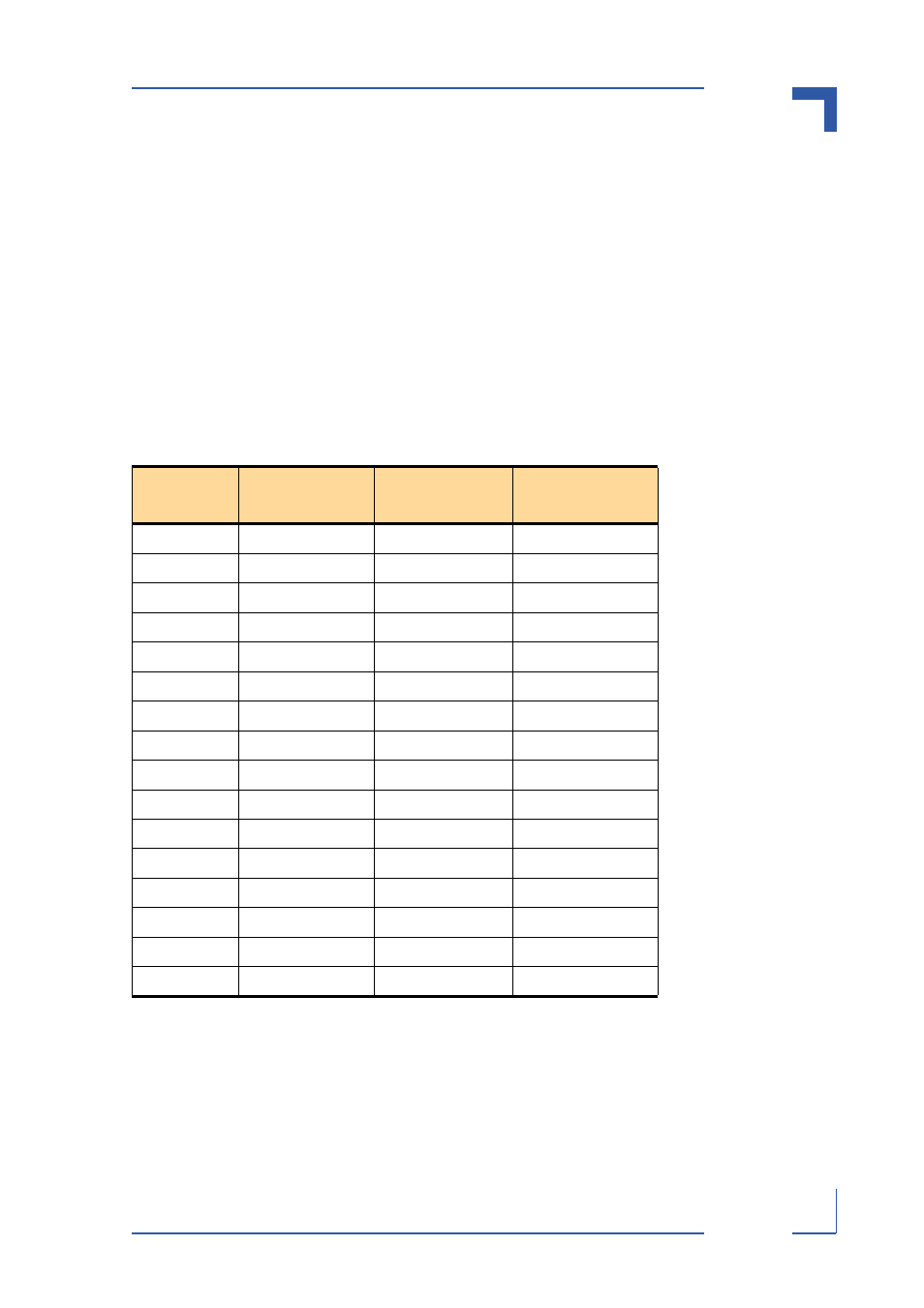
Switch LED Assignment
Table 3-19: Switch LED Assignment
Switch LED
Number
Base Interface Fabric Interface
Logical ATCA
Slot
1
SMCA/B (Ch 1)
-
ShMC (s)
2
Ch 2
Ch 1
(other Hub)
3
Ch 3
Ch 2
3
4
Ch 4
Ch 3
4
5
Ch 5
Ch 4
5
6
Ch 6
Ch 5
6
7
Ch 7
Ch 6
7
8
Ch 8
Ch 7
8
9
Ch 9
Ch 8
9
10
Ch 10
Ch 9
10
11
Ch 11
Ch 10
11
12
Ch 12
Ch 11
12
13
Ch 13
Ch 12
13
14
Ch 14
Ch 13
14
15
Ch 15
Ch 14
15
16
Ch 16
Ch 15
16