2 channel 5 interface, 1 ethernet fiber optic interface, Channel 5 interface - 7 – Kontron CP930 User Manual
Page 33: 1 ethernet fiber optic interface - 7, Con5 fiber optic receptacle, front panel view - 7, Cp930 functional description
CP930
Functional Description
ID 26683, Rev. 01
© 2003 Kontron Modular Computers GmbH
Page 2 - 7
2.3.2
Channel 5 Interface
Their are three variants of channel 5. One variant employs a standard Ethernet interface (RJ45)
on the front panel, the second variant has a standard Ethernet RJ45 connector onboard, and
the third variant has a duplex MT-RJ-type connector receptacle for interfacing to fiber optic links
on the front panel. This variant is described below.
2.3.2.1
Ethernet Fiber Optic Interface
The Ethernet fiber optic interface is realized using an Agilent HFBR-M Fiber Optic Transceiver.
These transceivers support full duplex 100Base-FX operation and are fitted with a duplex MT-
RJ-type connector receptacle for interfacing to fiber optic links. CON5 is implemented as Chan-
nel 1 when installed.
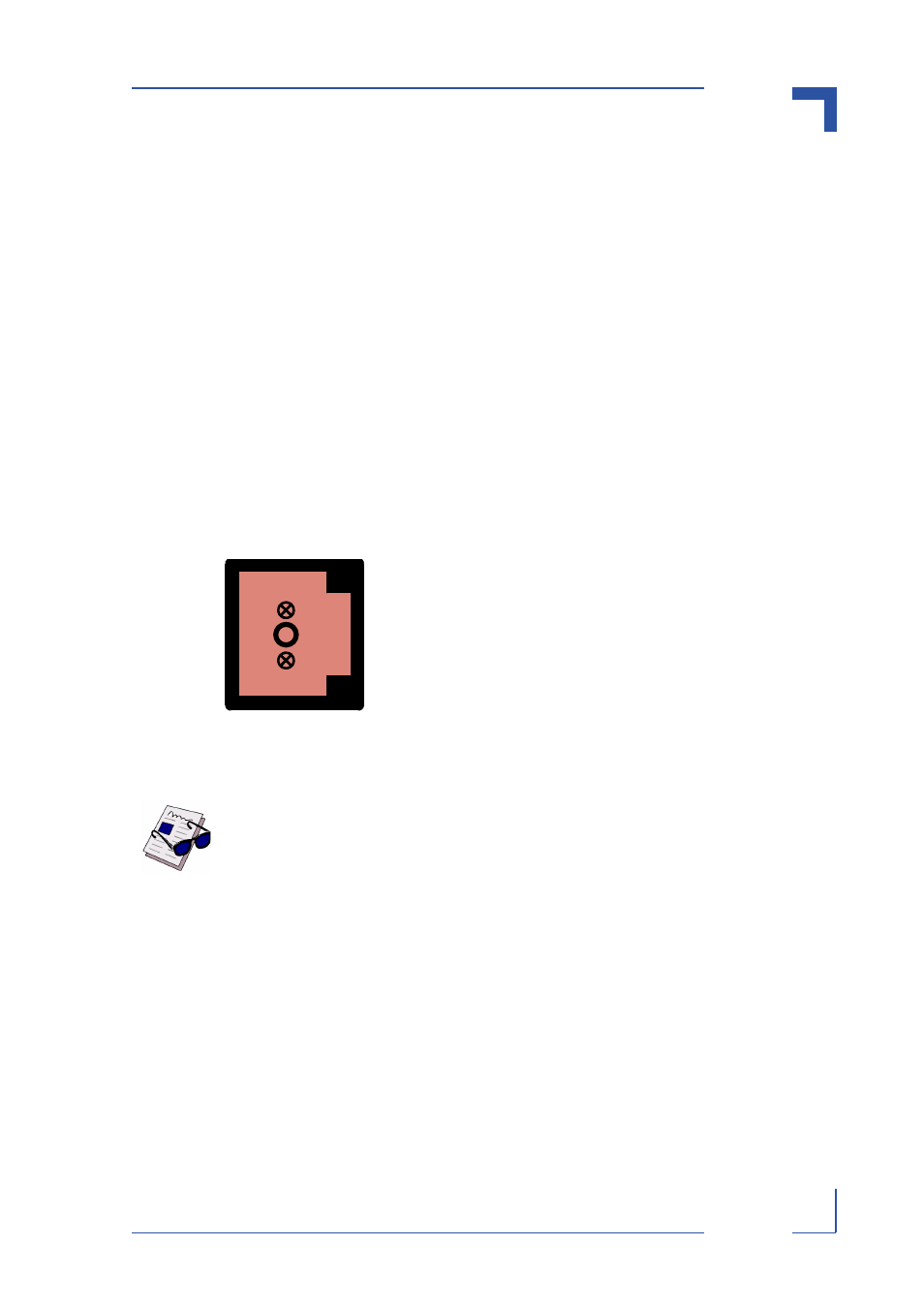
The following figure indicates the positioning of the transmit and receive receptacles and orien-
tation of the connectors and keying of the receptacles. The MT-RJ-type receptacle is designed
to support self-locking duplex MT-RJ-type male connectors. This ensures that the fiber optic
links are securely fastened to the receptacles.
Figure 2-3: CON5 Fiber Optic Receptacle, Front Panel View
Note...
The maximum length of cabling over which the Ethernet transmission can oper-
ate effectively depends upon the transceiver in use.
Tx
Rx