3 system interfaces, 1 ethernet wire cabling interface, System interfaces - 6 – Kontron CP930 User Manual
Page 32: Ethernet wire cabling interface - 6, Con3/4 and con6 connectors - 6, Con3, 4, 6, Functional description cp930
Functional Description
CP930
Page 2 - 6
© 2003 Kontron Modular Computers GmbH
ID 26683, Rev. 01
2.3
System Interfaces
2.3.1
Ethernet Wire Cabling Interface
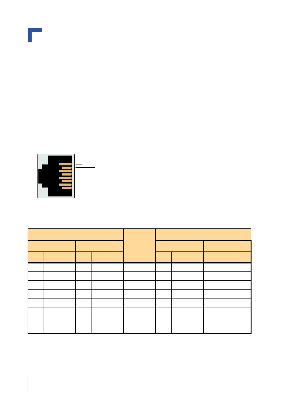
The Ethernet wire cabling interface is implemented using up to five 8-contact, female, RJ45
connectors. CON3 is implemented as channel 1-4, and CON4 is implemented as channel 5
when installed, this numbering being the front panel numbering and not the numbering of the
channels from the chip. As the Fast Ethernet controller is able to automatically detect the ca-
bling configuration and Ethernet standard in use, the pinout of the individual connectors is a
function of the implementation.
Figure 2-2: CON3/4 and CON6 Connectors
The following figure and table indicate the pin assignment and
signal function for each connector as a function of the imple-
mentation.
The signal pinouts on the left side of the table are for the stan-
dard Media Dependent Interface (MDI) using appropriate
CAT5 UTP cabling for the Ethernet standard in use.
The signal pinouts on the right side of the table are for the Me-
dia Dependent Interface Crossed (MDIX) using appropriate
CAT5 UTP cabling for the Ethernet standard in use.
In addition, the input / output status of each signal is also in-
dicated in the table.
Table 2-1: Pinouts of CON3, CON4 and CON6 Based on the Implementation
MDI / Standard Ethernet Cable
PIN
MDIX / Crossed Ethernet Cable
10BASE-T
100BASE-TX
10BASE-T
100BASE-TX
I/O
SIGNAL
I/O
SIGNAL
I/O
SIGNAL
I/O
SIGNAL
O
TX+
O
TX+
1
I
RX+
I
RX+
O
TX-
O
TX-
2
I
RX-
I
RX-
I
RX+
I
RX+
3
O
TX+
O
TX+
-
-
-
-
4
-
-
-
-
-
-
-
-
5
-
-
-
-
I
RX-
I
RX-
6
O
TX-
O
TX-
-
-
-
-
7
-
-
-
-
-
-
-
-
8
-
-
-
-
2
4
6
8
1
3
5
7
CON3, 4, 6