FEBCO 805YD DuraCheck In-Line Design Double Check Valve Assemblies User Manual
Installation instructions, Double check detector assemblies, Sizes
IS-F-805Y/805YD/806YD
I N S T A L L A T I O N I N S T R U C T I O N S
Installation Instructions
1. Consult local codes for specific installation requirements and restrictions
applicable to your area. It is recommended that system supply pressure
be at least 20psi (138 kPa).
2. These instructions apply only to Series 805Y sizes
3
⁄
4
" – 2" (20 – 50mm),
805YD sizes 2
1
⁄
2
" – 10" (65 – 250mm), and 806YD sizes 3" – 10"
(80 – 250mm). The valves may be installed only in the orientation/flow
directions as shown. The gate valves may be rotated, as permitted by
the flange bolt pattern, on vertical installations only.
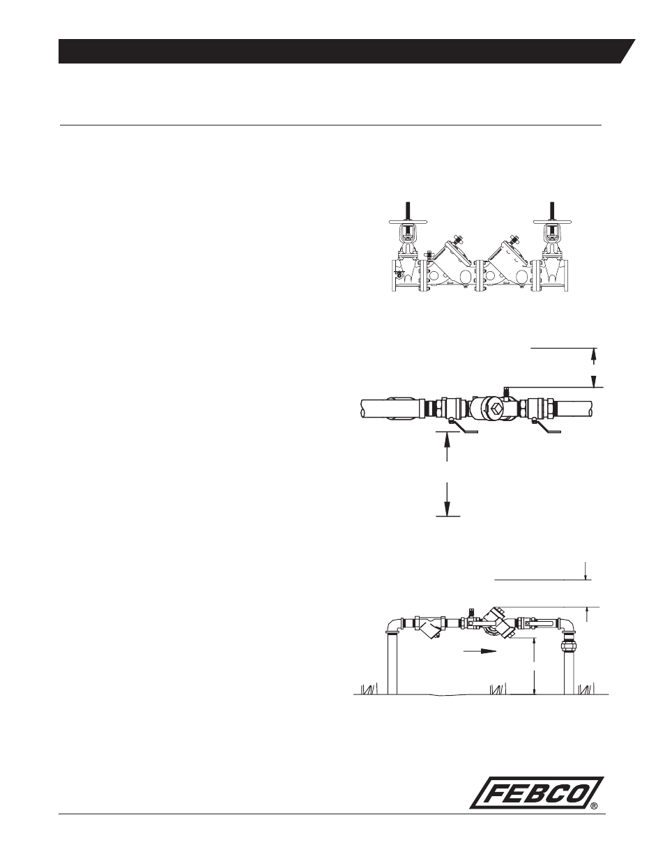
3. The valve assembly must be installed where it is accessible for periodic
testing and maintenance. Clearances shown in the installation views
apply to exterior, interior and pit/vault installations and are only recom-
mendations. These minimums do not apply to removable protective
enclosures. Refer to local codes for actual requirements in your area.
4. PRIOR TO INSTALLING THE VALVE INTO THE LINE, FLUSH THE
SUPPLY LINE OF ALL FOREIGN MATERIAL. Failure to flush the
supply line may cause the check valves to become fouled and require
disassembly and cleaning.
5. Lift the assembly by the valve body. DO NOT LIFT THE ASSEMBLY
BY CONNECTING TO THE VALVE HANDLES, STEMS, OR
BYPASS PIPING. On 2
1
⁄
2
" – 10" (65 – 250mm) units lift eyes are bolted
to the check covers.
6. After installation SLOWLY fill the assembly with water and bleed air
from the body using the # 2, # 3 and # 4 test cocks. Test the valve
assembly to ensure correct operation.
NOTE: All assemblies are tested at the factory for proper operation and
leakage. If the valve does not pass the field test, it is most likely due to
a fouled check valve. This is not covered by the factory warranty. The
valve cover(s) must be removed and the check seats inspected and
cleaned. Any damage or improper operation caused by pipeline debris
or improper installation/start-up is not included in the factory warranty.
In case of a possible warranty claim, contact your local supplier or
FEBCO Representative. DO NOT REMOVE THE VALVE ASSEMBLY
FROM THE PIPELINE.
7. The assembly must be protected from freezing and excessive pressure
increases. Pressure increases can be caused by thermal expansion or
water hammer. These excessive pressure situations must be elimi-
nated to protect the valve and system from possible damage.
8. Plastic testcock plugs and tethers are provided for the Series 805Y
(loose in box) for areas that require them.
Series 805Y, 805YD, 806YD
Double Check Detector Assemblies
Sizes:
3
⁄
4
" – 10" (20 – 250mm)
6" (150mm) Min
12" (300mm) Min
12" (300mm) Min
Horizontal Installation for the DC Series 805YD
(Top View, Shown with Strainer)
Horizontal Installation for the Series 805YD
(Top View, Shown with Strainer)
Flow
Figure 1
Figure 2
18" (450mm) Min