212fsa, 212fs, Controlli e funzioni ita uk controls and functions – FBT MITUS User Manual
Page 10
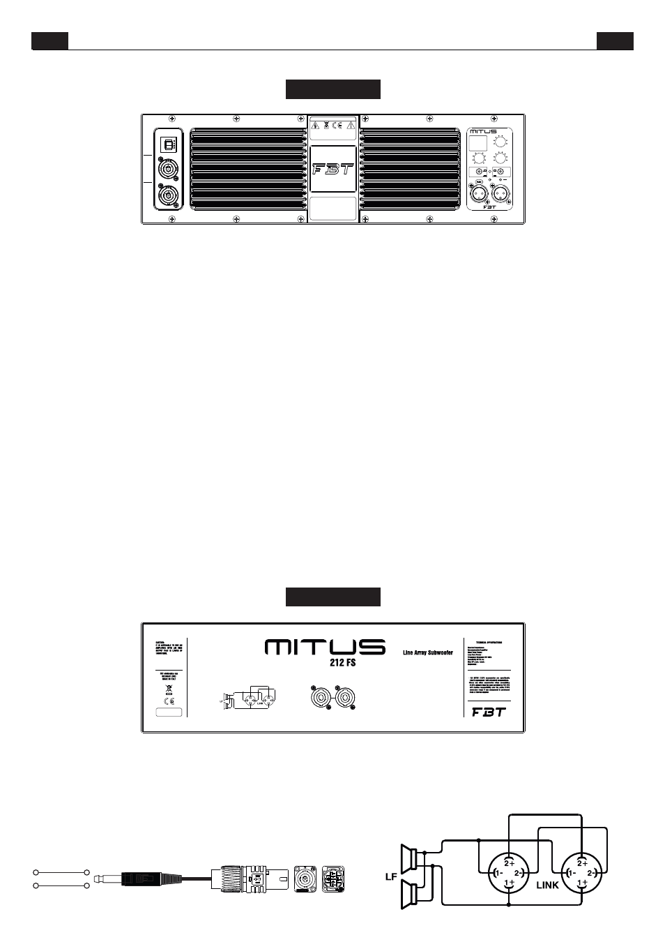
PIN 1+
TIP
PIN 1-
SLEEVE
POWER
CONSUMPTION
: 640W
AC LOOP OUT
220-230V
ac
50/60Hz
16.8A max
AC INPUT
220-230V
ac
50/60Hz
2.8A max
DO NOT EXCEED RA
TED MAX CURRENT DRA
W FROM AC LOOP OUTPUT CONNECTOR
TO PREVENT THE RISK OF FIRE OR ELECTRIC
SHOCK NEVER EXPOSE THIS EQUIPMENT
TO RAIN OR MOISTURE
RISK OF ELECTRIC SHOCK DO NOT OPEN
CAUTION
MADE IN ITALY
All MITUS
accessories are specifically
rated in agreement with
structural
computati ons.
Nev er
u se
other
accessories
when
assembling
the
cabinets than the ones provided by FBT:
FBT will decline responsibility over the
entire MITUS accessories range if any
component is purchased from a different
supplier.
ON
GND
LIFT
PHASE
180!
0!
+6dB
0
0
0
0
0.5
1
1.5
2
2.5
3
3.5
PRESET
LEVEL
DELAY
mt.
1- HUNG
2- HUNG PUNCH
3- HUNG with INFRA
4- GROUND
5- GROUND PUNCH
6- GROUND with INFRA
7- GND CARDIOID FRONT
8- GND CARDIOID REAR
212 FSA
1
2
3
4
5
6
7
8
IN
LINK
PEAK
LMT
PRT
OFF
ON
ACTIVE SUBWOOFER
212FSA
8 Ohm
1000 W RMS
2000 W
500 W
50 Hz - 120 HZ
99 dB
134 / 138 dB
omnidirectional
LINK
IN
212FS
CONTROLLI E FUNZIONI
ITA
UK
CONTROLS AND FUNCTIONS
*SPEAKON is a registered trademark of NEUTRIK
*SPEAKON è un marchio registrato NEUTRIK
DELAY:
LEVEL:
GND LIFT:
ON:
PHASE:
PEAK:
LMT/PRT:
IN-LINK:
Controllo di una linea di ritardo digitale che agisce sul segnale di
ingresso; in questo modo è possibile compensare il disallineamento sul
piano verticale di sub e satellite. Il delay è espresso in metri e va da 0.5 a 3.5
metri a passi di 50 cm.
Regola il il livello generale del segnale.
Interruttore per la separazione elettrica tra il circuito di massa e il
circuito di terra onde evitare possibili “loop” di massa, causa di fastidiosi
ronzii.
Indica l'attivazione del sistema.
Il controllo Phase consente di ottimizzare l'allineamento di fase,
cioè di ottenere una risposta in frequenza uniforme nella zona di incrocio tra
sub e satellite. Nella posizione 0° l'emissione sonora del sub è in fase con il
segnale di ingresso; nella posizione 180° l'emissione sonora è in contro-fase
con il segnale di ingresso; questo controllo consente di ottenere ulteriore
flessibilità nella messa a punto del subwoofer ottimizzandone le prestazioni.
L'accensione di questo led indica che il livello del segnale è prossimo
alla saturazione.
L'accensione del led indica il malfunzionamento del sistema
dovuto ad un guasto dell'amplificatore interno o all'intervento dei circuiti di
limitazione per evitare sovraccarico termico.
Prese di ingresso/uscita bilanciate; “IN” consente il collegamento
di un segnale preamplificato come ad esempio quello in uscita da un mixer;
“LINK” permette il collegamento di più diffusori con lo stesso segnale.
PRESET: Seleziona 8 preset ad ognuno dei quali corrisponde una
configurazione di diffusori, in base alle preferenze personali e all'acustica
dell'ambiente di ascolto ( vedi sezione PRESET ).
Le prese Speakon sono collegate in parallelo; utilizzare una presa per il
collegamento del box all’uscita di un amplificatore di potenza, l’altra per
collegare un secondo box.
È necessario scegliere cavi per diffusori con un diametro sufficiente in
funzione della lunghezza totale del collegamento. La resistenza introdotta
da un cablaggio inadeguato verso i diffusori riduce sia la potenza in uscita
sia il fattore di smorzamento dell’altoparlante.
Speakon connectors are connected in parallel mode. One connector can be
used to connect the box to the output of a power amplifier, the other to
connect to a second box.
Loudspeaker cables shall have the adequate diameter, depending on the
overall lenght of the connection. The resistance introduced by an inadequate
wiring towards the loudspeakers would reduce both the power output and
the damping factor of the loudspeaker.
DELAY:
LEVEL:
GND LIFT:
ON:
PHASE:
PEAK:
LMT/PRT:
IN-LINK:
Control of a digital delay line acting on the input signal; in this way it
is possible to make up for the vertical misalignment of sub and satellite. The
Delay is expressed in metres and goes from 0.5 to 3.5 m with 50cm steps.
It adjusts the signal general level.
A switch for the electric separation between the ground and earth
circuits; this can be useful in order to remove the irritating noises caused by
ground loops.
Indicates that the system is on.
The Phase control allows to optimize phase alignment, i.e. to obtain
a uniform frequency response in the crossover area between the sub and the
satellite. When it is set at 0°, the sound emission is in phase with the input
signal; when it is set at 180° the sound emission is in counterphase with the
input signal; thanks to this control, subwoofer adjustment will be even more
flexible with a consequent performance optimization.
When this LED lights up, it indicates that the signal is reaching
saturation.
If this LED lights up, there is a system malfunction due to an
internal amplifier failure or to the intervention of current limiting circuits
against thermal overload.
Balanced input/output sockets; “IN” allows to connect a pre-
amplified signal such as that coming, for instance, from mixer output. “LINK”
allows to connect multiple speakers to the same signal.
PRESET: Selects 8 presets, each of whom corresponds to a specific
speaker configuration according to users' personal preferences and to the
acoustics of the listening area (see PRESET section.)
7