Typical 10 v/m power required – model 5400 series, Typical automated radiated immunity test setup – ETS-Lindgren 5411 GTEM! Test Cell User Manual
Page 37
GTEM! Use
|
37
T
YPICAL
10 V/
M
P
OWER
R
EQUIRED
–
M
ODEL
5400
S
ERIES
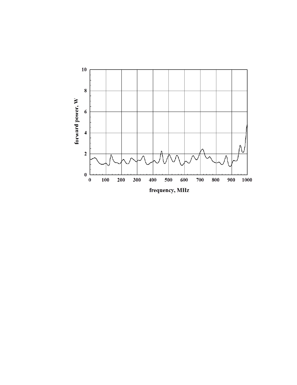
Following is the typical measured power required for 10 V/m at a 0.9-m septum
height (40 cm height above floor and 80 cm septum height) in a
Model 5400 Series.
T
YPICAL
A
UTOMATED
R
ADIATED
I
MMUNITY
T
EST
S
ETUP
Following is a typical setup for conducting radiated immunity testing using
automated control techniques. Testing can be completely automated if it is
possible to define a test signal response from the EUT, which can be sensed by
the controlling computer. A signal generator is shown with an external modulation
source so that the modulation characteristics can be matched, if desired, to
signals internal to the EUT. The output of the signal generator is applied to the
RF power amplifier, which in turn drives the GTEM!. Application of the signal to
the GTEM! input produces the test signal between the septum and the floor of
the GTEM!. Internal to the GTEM!, an optional broadband, high-level isotropic
probe monitors the level of the applied signal. An isotropic field probe may be
used to sense the applied field at different locations and report actual electric
field strength values.
The EUT is installed in the GTEM! in the approximate center of the test volume.