Introduction – Dynojet Data Link Module - OBDII User Manual
Page 24
Data Link Module-OBDII Installation and User Guide
A P P E N D I X A
Introduction
A-2
. . . . . . . . . . . . . . . . . . . . . . . . . . . . . . . . . . .
INTRODUCTION
There are four basic configurations for the Dynojet Data Link Module-OBDII (DJDLM-
OBDII). Each DJDLM-OBDII ships with the ability to be configured using any of the
four methods described below. Dynojet recommends the DJDLM-OBDII be set up as a
client on your wireless network. If this is not possible, it is recommended to use a
direct connection to your dynamometer PC with a category 5 crossover cable.
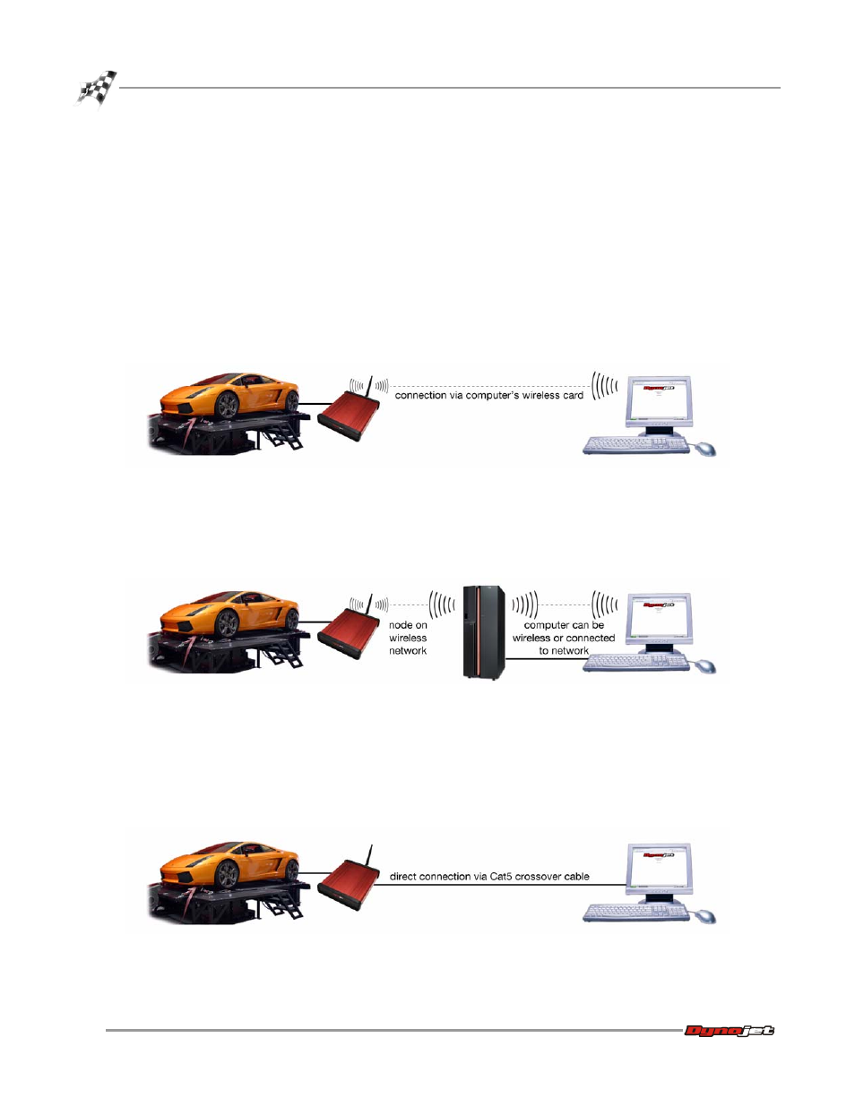
Stand Alone Wireless—directly connects to your PC via your PC’s wireless card. This
is the factory default and requires no special configuration. Refer to “Configuring the
DJDLM-OBDII as a Stand Alone Wireless Device” on page A-5 for more information.
Figure A-1: Stand Alone Wireless Configuration
Wireless Client—connects through your wireless network as a node on the wireless
network. Refer to “Configuring the DJDLM-OBDII as a Wireless Client” on page A-6 for
more information.
Figure A-2: Wireless Client Configuration
Category 5 Crossover Cable—directly connects to your PC with a category 5
crossover cable. This is the fastest data transfer option available. No configuration is
needed to the DJDLM-OBDII when using the crossover cable; just plug and play. Refer
to “Configuring the DJDLM-OBDII with a Category 5 Crossover Cable” on page A-8 for
more information.
Figure A-3: Category 5 Crossover Cable Configuration