Cable routing, Connecting the dyno electronics and shop air – Dynojet 224: Pit Installation Guide User Manual
Page 27
I N S T A L L A T I O N
Cable Routing
Version 4
In Ground Model 224 Automotive Dynamometer Installation Guide
2-7
. . . . . . . . . . . . . . . . . . . . . . . . . . . . . . . . . . .
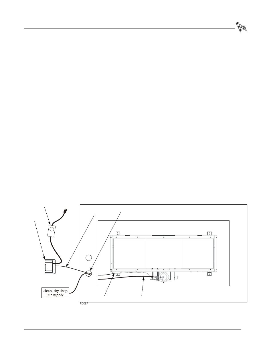
CABLE ROUTING
Use the following instructions to route the cables. You will need to route the cables
before installing the pit covers.
C
ONNECTING
THE
D
YNO
E
LECTRONICS
AND
S
HOP
A
IR
You will need the following parts:
• 318110301 Power Cord
• 42924250
25-pin Cable
• 53415040
Power Supply
• 76199003N Dyno Electronics
1
Route the 25-pin cable from the Breakout board, through one of the PVC conduits
in the pit, and to the dyno electronics.
Refer to page 1-10 for more information on connecting to the dyno electronics.
Refer to page 2-9 for more information on wiring the Breakout board.
2
Route the air hose from your shop air supply, through one of the PVC conduits in
the pit, and connect the air hose to the T fitting on the dyno brake solenoid.
Note: The air brake comes installed with a hose barb for a 3/8-inch inside
diameter air hose. If your hose does not have an inside diameter of 3/8-inch then
you will need an air hose nipple (1/4-inch NPT) to connect your clean, dry shop
air supply to the dyno. Once the pressure is connected, the air brake is ready to
use.
3
Connect the power supply to the dyno electronics. Plug the power supply into
your power source.
Figure 2-4: Route the Cables
power supply for
dyno electronics
breakout board
dyno
electronics
dyno electronics
cable
shop air
pit conduit