Wiring the dynoware ex+ modules, Figure 16: attach the dynoware ex+ cables – Dynojet 250: DynoWare EX+ Upgrade User Manual
Page 17
I N S T A L L A T I O N G U I D E
Installation
Version 3
DynoWare EX+ Upgrade Installation Guide
11
W
IRING
THE
D
YNO
W
ARE
EX+ M
ODULES
1
Place the DynoWare EX+ modules in a safe location in the shop that is close
enough to the computer and the dyno for the cables to reach.
2
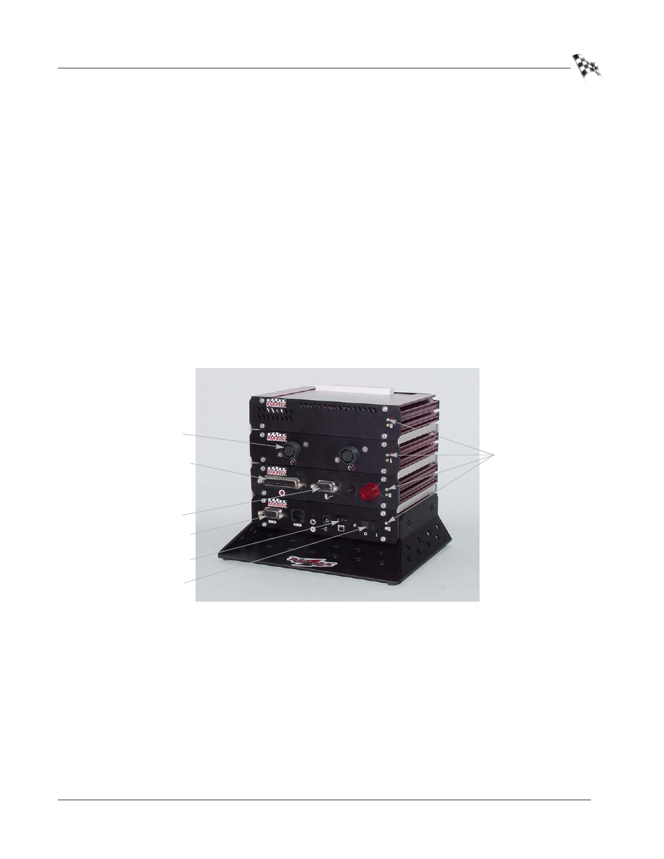
Attach the cables to the DynoWare EX+ modules. Refer to Figure 16 for cable
placement.
• Attach the 9-pin shielded serial cable from the PC to the RS-232 socket on the
CPU module. Tighten the screws.
• Attach the 25-pin shielded cable from the dynamometer to the Dynamometer
Input/Output module. Tighten the screws.
• Attach the 9-pin connector from the hand-held pendant to the Dynamometer
Input/Output module. Tighten the screws.
• Attach the 3-pin plug from the power supply to the CPU module with the flat
side facing down.
3
Plug the power supply into an electrical outlet.
4
Turn the power switch on at the CPU module and verify operation with WinPEP.
Note: If you have an air brake, the air brake is now controlled from the remote
pendant.
Figure 16: Attach the DynoWare EX+ Cables
primary inductive
pickup socket
9-pin, hand-held
pendant
25-pin socket
9-pin, RS-232 socket
3-pin power plug
power LEDs
power switch