Installing the breakout board, Figure 13: install the vibration dampening mounts, Figure 14: secure the breakout board and cover – Dynojet 250: DynoWare EX+ Upgrade User Manual
Page 15
I N S T A L L A T I O N G U I D E
Installation
Version 3
DynoWare EX+ Upgrade Installation Guide
9
I
NSTALLING
THE
B
REAKOUT
B
OARD
1
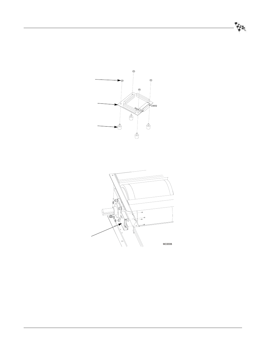
Install the four rubber vibration dampening mounts to the Breakout board using
four No. 8 nuts.
Figure 13: Install the Vibration Dampening Mounts
2
Secure the Breakout board cover and board to the dyno using four No. 8 screws.
Note: Be sure the large data plug on the Breakout board is facing towards the
front of the dyno (away from the drum).
Figure 14: Secure the Breakout Board and Cover
breakout board
nuts
dampening
mounts
Breakout board
and cover
This manual is related to the following products: