Wiring instructions, Warning – Code 3 Excalibur User Manual
Page 5
5
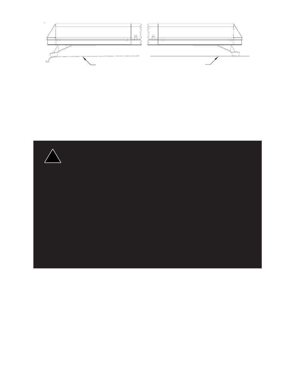
FIGURE 4
Once the light bar is level and centered, mark the holes through the mounting tabs and remove the
light bar from the vehicle. Make sure that the drill will not damage anything when penetrating the roof.
Drill the mounting holes and remove any burrs. Attachment can be made using 1/4" cap screws,
toggle bolts, or other fasteners as may be convenient. Use sealant as necessary to prevent water
leakage into the vehicle.
Wiring Instructions
Larger wires and tight connections will provide longer service life for components. For high
current wires it is highly recommended that terminal blocks or soldered connections be used with
shrink tubing to protect the connections. Do not use insulation displacement connectors (e.g.
3M
®
Scotchlock type connectors). Route wiring using grommets and sealant when passing
through compartment walls. Minimize the number of splices to reduce voltage drop. High
ambient temperatures (e.g. underhood) will significantly reduce the current carrying capacity of
wires, fuses, and circuit breakers. Use "SXL" type wire in engine compartment. All wiring should
conform to the minimum wire size and other recommendations of the manufacturer and be
protected from moving parts and hot surfaces. Looms, grommets, cable ties, and similar
installation hardware should be used to anchor and protect all wiring. Fuses or circuit breakers
should be located as close to the power takeoff points as possible and properly sized to protect
the wiring and devices. Particular attention should be paid to the location and method of making
electrical connections and splices to protect these points from corrosion and loss of conductivity.
Ground terminations should only be made to substantial chassis components, preferably directly
to the vehicle battery. The user should install a fuse sized to approximately 125% of the maxi-
mum Amp capacity in the supply line to protect against short circuits. For example, a 30 Amp
fuse should carry a maximum of 24 Amps. DO NOT USE 1/4" DIAMETER GLASS FUSES AS
THEY ARE NOT SUITABLE FOR CONTINUOUS DUTY IN SIZES ABOVE 15 AMPS. Circuit
breakers are very sensitive to high temperatures and will "false trip" when mounted in hot
environments or operated close to their capacity.
WARNING!
!
Before attempting to connect wiring refer to wire tag attached to the lightbar's main cable. Each wire in the cable
controls a separate lightbar function as described in the wire tag.
The only significant difference between the Excalibur with optional ArrowStik
®
and a conventional
Excalibur
®
, is the additional, thinner cable exiting the bottom of the lightbar. The larger cable is the lightbar power
cable. Route the wiring cable into the engine or passenger compartment, taking care to use grommets and to
apply sealant around openings to keep water out. It is advisable to leave an extra loop of cable when installing the
light bar to allow for future changes or reinstallations. Connect the black lead to a solid frame ground (earth),
preferably, the (-) or ground (earth) side of the battery. Connect the wires as directed by the wiring instructions on
the cable.
Curved Roof
Flat Roof
Place Feet on
Curved Portion