Unpacking & pre-installation, Installation & mounting, Warning – Code 3 Excalibur User Manual
Page 3: Hook-on mounting
3
Unpacking & Pre-installation
Carefully remove the light bar and place it on a flat surface, taking care not to scratch the lenses or damage the cable
coming out of the bottom. Examine the unit for transit damage, broken lamps, etc. Report any damage to the carrier and
keep the shipping carton.
Standard light bars are built to operate on 12 volt D.C. negative ground (earth) vehicles. If you have an electrical system
other than 12 volt D.C. negative ground (earth), and have not ordered a specially wired light bar, contact the factory for
instructions.
Test the unit before installation. To test, touch the black wire to the ground (earth) and the other wires to +12 volts D.C.,
in accordance with the instructions attached to the cable (an automotive battery is preferable for this test). A battery
charger may be used, but please note that some electronic options (flashers, stingrays, etc.) may not operate normally
when powered by a battery charger. If problems occur at this point, contact the factory.
Installation & Mounting
MOUNTING HARDWARE - All mounting hardware is packed in a small box inside the main carton. Four standard kits
are available: (1) Hook-On Type, (1) Tow and Recovery and (2) Permanent Types. These are discussed in detail later.
Note: Hook-on mounting for "gutterless" type vehicles will require a special hook for mounting. Several special
application hooks are available. Contact the factory for details.
Utilizing non-factory supplied screws and/or mounting brackets and/or the improper
number of screws may result in loss of warranty coverage on the equipment.
WARNING!
!
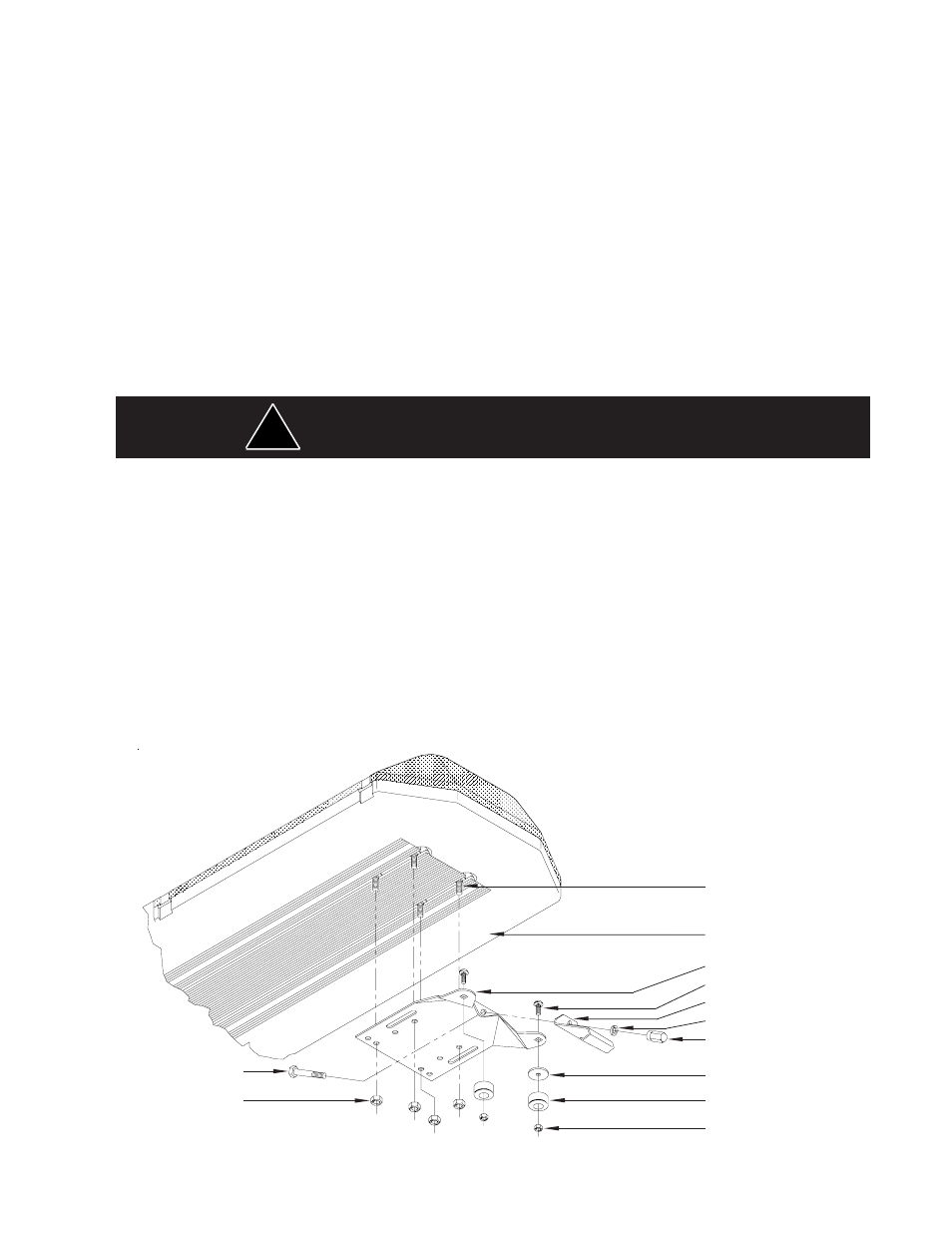
Mounting Bracket
Bottom of Lightbar
1/4-20 Carriage Bolt
5/16" Split Lockwasher
5/16" Trim Nut
(Do Not Overtighten)
Plastic Shim (if needed)
Rubber Foot
1/4" Acorn Nut
5/16" Cap Screw
5/16" Nut
FIGURE 1
Hook-on Mounting
Begin the installation by attaching the rubber feet to the mounting brackets using the black 1/4"
carriage bolts and 1/4" nuts provided. See Figure 1. (Do not install shims at this time). Place the
light bar upside down on a table or other work surface, being careful not to scratch the lenses. Slide
the 5/16" carriage bolts into the frame. Secure the mounting brackets finger tight so they support the
weight of the light bar, but still are positionable. Locate the vehicle on a level surface. Place the light
bar on the roof of the vehicle. Place a soft pad in the center of the roof to protect the paint. The
mounting brackets must be placed so that the rubber feet are resting on the curved section of the
roof, see Figure 2. This is the strongest part of
the roof. Once the light bar is centered, tighten
the mounting bracket to the light
bar. Using a tape measure and a level, center
the light bar from side to side
and locate a position on the roof where the
light bar is level.
Gutter Hook
5/16-18 Carriage Bolt