Chapter 2: installation, Page c-1 – Salter Brecknell 750 Series User Manual
Page 9
Page C-1
CHAPTER 2: INSTALLATION
2.1
ABS ENCLOSURE (S750/S750-8)
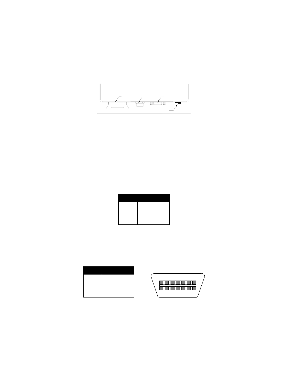
For indicators contained in the standard ABS enclosure, the rear panel contains all connectors
necessary to make the appropriate connections to the weigh platform, printer, remote display and
power supply.
DC Jack
Serial
Port
LOAD CELL
Setup/Calibration Switch
Port
Figure 2-1: S750/S750-8 ABS Enclosure Rear Panel
2.1.1 CONNECTING THE WEIGH PLATFORM
The indicators mounted in an ABS enclosure ship with a 15 ft shielded load cell cable for
connection to weigh platform’s load cell(s) or junction box.
1. Plug the cable’s 14-pin Centronics-type connector into the load cell port on the rear
panel of the indicator.
2. Wire the bare wires and shield to the weigh platform’s load cell(s) or junction box using
the color codes shown in Figure 2-2.
Color
Wire Name
RED
+Excitation
BLK
- Excitation
GRN
+Signal
WHT
- Signal
Figure 2-2: Color Codes for Shielded Load Cell Cable
3. If you do not wish to use the shielded load cell cable, you may use own, following the
pin assignments shown in Figure 2-3. (A 14-pin Male Centronics-type connector is
required).
Pin Nos.
Pin Name
1/8
+Excitation
3/10
- Excitation
5/12
+Signal
7/14
- Signal
7
1
5
3
14
12
10
8
Figure 2-3: Pin assignments for the Load Cell Port