Page c-1 – Salter Brecknell 750 Series User Manual
Page 10
Page C-1
2.1.2 CONNECTING THE SERIAL PRINTER, REMOTE DISPLAY OR COMPUTER
The S750 series indicator comes standard with two serial ports, designated COM1 and COM2.
COM1 is a full duplex, RS-232 port designed for connection to either a PC or a
serial printer. COM2 is a simplex, RS-232 / Passive 20 mA Current Loop port
designed for connection to a remote display.
For indicators housed in an ABS enclosure, both COM ports are wired to one physical connector,
a DSUB9 female. As a result, you must use a “Y” interface cable (not included) to
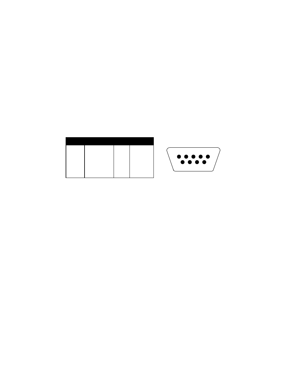
gain access to COM2. Figure 2-4 shows the serial port pinout. Refer to Appendix B
for some suggested cable diagrams. (A 9-pin pin Male D-type connector is
required).
1. Plug the serial printer or computer communication cable (not included) directly into the
DSUB9 serial port connector or into the port labeled COM1 on the “Y” interface cable.
2. Plug the remote display cable (not included) directly into the port labeled COM2 on the
“Y” interface cable.
Pin No.
Pin Name
2
Receive Data
3
Transmit Data
4
Transmit Data
Port
COM1
Signal Level
RS-232
COM1
RS-232
RS-232
COM2
5
Signal Ground
RS-232
Both
7
CL +
20 mA
COM2
8
CL –
20 mA
COM2
2
3
5
4
8
7
Front View
Figure 2-4: Pin assignments for the DSUB9 serial port connector
2.1.3 CONNECTING THE POWER SUPPLY
1. The indicator ships standard with an internal AC to DC adapter. Simply plug the AC line
cord into a standard wall outlet.
2. If the indicator was shipped with the optional external AC adapter, simply plug the AC
adapter into the indicator’s DC Power Jack first, and then plug into a standard wall
outlet. Make sure that the AC voltage appearing at the wall outlet matches the
input voltage marked on the AC adapter.