Salter Brecknell 750 Series User Manual
Page 12
Page C-1
2.2.2 CONNECTING THE SERIAL PRINTER, REMOTE DISPLAY OR COMPUTER
The S750 series indicator comes standard with two serial ports, designated COM1 and COM2.
COM1 is a full duplex, RS-232 port designed for connection to either a PC or a
serial printer. COM2 is a simplex, RS-232 / Passive 20 mA Current Loop port
designed for connection to a remote display.
For indicators housed in a Stainless Steel enclosure, COM1 is realized in J6 while COM2 is
realized in both J10 (RS-232) and J7 (CL). Connection assignments for all serial
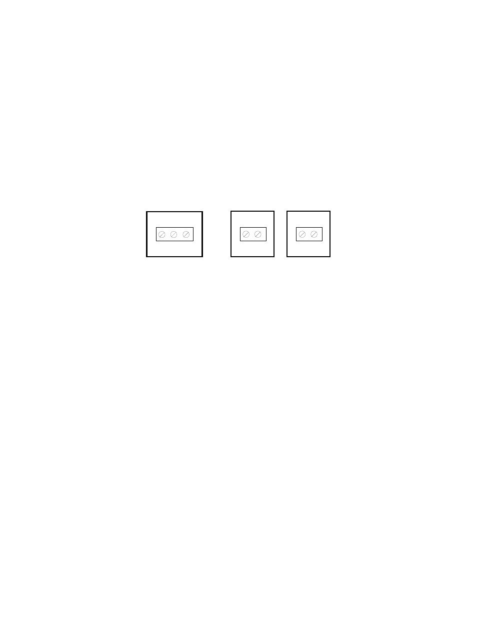
communication terminals are shown in Figure 2-7.
1. Connect your serial printer or computer communication cable (not included) to terminal
J6 on the main board.
2. Connect your remote display communication cable (not included) to terminal J10 or J7
on the main board
TXD RXD GND
J6
TXD GND
J10
CL+ CL–
J7
Figure 2-7: Connection assignments for all serial communication terminals
2.2.3 CONNECTING THE POWER SUPPLY
1. The indicator ships standard with an internal AC to DC adapter. Simply plug the AC line
cord into a standard wall outlet.
2. If the indicator was shipped with the optional external AC adapter, simply plug the AC
adapter into the indicator’s DC Power Jack first, and then plug into a standard wall
outlet. Make sure that the AC voltage appearing at the wall outlet matches the
input voltage marked on the AC adapter.