Salter Brecknell 400ES User Manual
Page 8
Page 2 - 2
2.1.1 CONNECTING THE WEIGH PLATFORM
1. Connect your shielded load cell cable (not included) to terminal J8 on the main
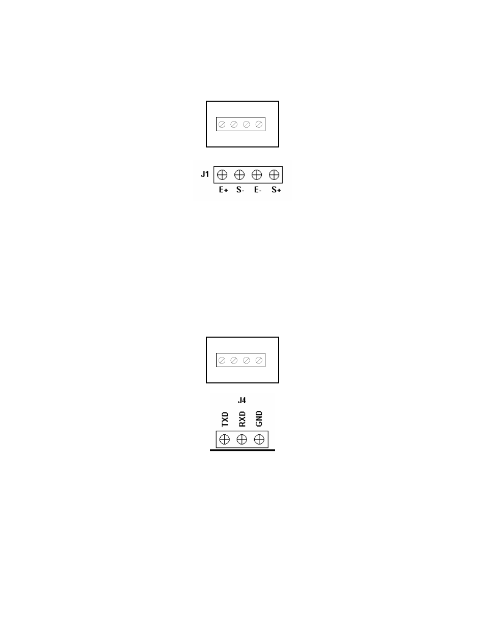
board. Connection assignments for the Load Cell Terminals are shown in Figures 2-
2 and 2-2a.
S–
E–
S+
J8
E+
Figure 2-2: Connection assignments for the Load Cell Terminal (J8)
Figure 2-2a: Connection assignments for the Load Cell Terminal – Newer Units
2.1.2 CONNECTING THE SERIAL PRINTER, REMOTE DISPLAY OR COMPUTER
The 400ES indicator comes standard with one full duplex RS-232 port, designed for
connection to either a PC or a serial printer. The same port may be also used as a simplex,
RS-232 port designed for connection to a remote display.
For indicators housed in a Stainless Steel enclosure, this is realized in J3. Connection
assignments for all serial communication terminals are shown in Figure 2-3. NOTE: Do not
connect any RS-232 equipment to the “+5V” terminal.
1. Connect your serial printer, remote display or computer communication cable (not
included) to the appropriate terminal on the main board.
TXD RXD GND
J3
+ 5V
Figure 2-3: Connection assignments for the serial communication terminal
Figure 2-3a: Connection assignments for the serial communication terminal –
Newer Units
2.1.3 CONNECTING THE POWER SUPPLY
The 400ES indicator ships with an AC line cord attached to the indicator. Simply plug the
unit into a standard wall outlet.
Older units shipped with an external AC adapter.
1. Simply plug the AC adapter into the indicator’s DC Power Jack first, and then plug
into a standard wall outlet. Make sure that the AC voltage appearing at the wall
outlet matches the input voltage marked on the AC adapter.