Salter Brecknell 200ES User Manual
Page 46
E-2
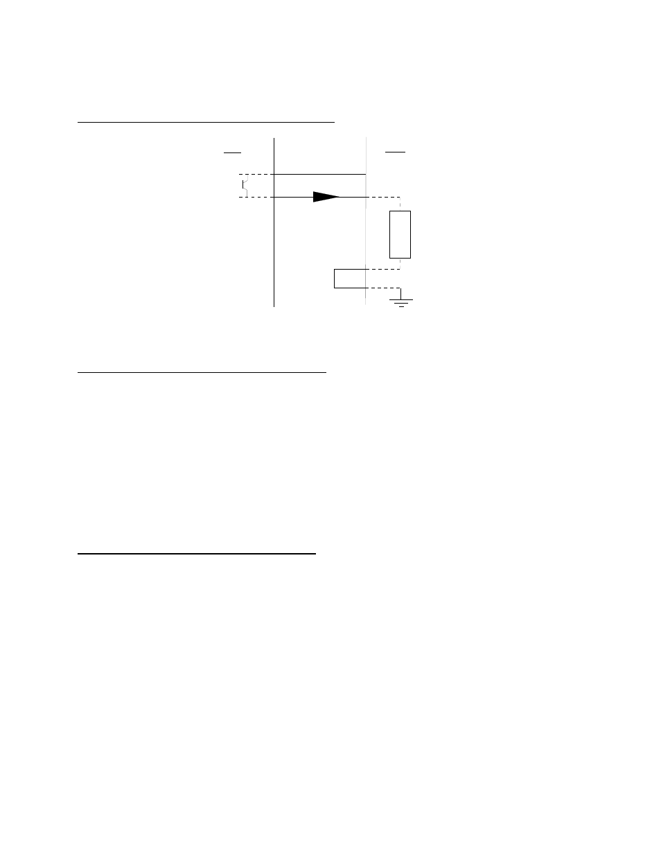
Here is a suggested connection diagram for a PLC:
+24 VDC
R
L
I
L
or AA
or BB
+
200
PLC
GND
-
4-20A
4-20B
NOTE 1
: Do NOT connect the indicator ground to the PLC ground.
Here is how to test to see if it is working correctly:
1. Configure and calibrate the indicator to your load device. Ensure the weighing function is
working properly.
2. Connect the AA (4-20A) and BB (4-20B) output wires to an external 24 VDC power supply
and 250 Ω resistor as shown in the above test diagram.
3. When the indicator is displaying zero, the output should be 4 mA. Since V=IR, you should
measure 1 VDC across R
L
.
4. When the indicator is displaying the full-scale load, the output should be 20 mA. Again, since
V=IR, you should measure 5 VDC across R
L
.
Here is how you fine-tune the output using F23:
1. Enter the Setup Menu and scroll to F23. For directions on entering the Setup Menu, see
Chapter 3 of the manual.
2. Push the down (ZERO) key once. The indicator outputs 4 mA and displays a number.
3. While monitoring the voltage across R
L
, use the right (PRINT) or left (TARE) keys to change
the displayed value until the measured voltage is exactly 1 VDC.
4. Press the SET (Net/Gross) key to save. The indicator outputs 20 mA and displays another
number.
5. While monitoring the voltage across R
L
, use the right (PRINT) or left (TARE) keys to change
the displayed value until the measured voltage is exactly 5 VDC.
6. Press the SET (Net/Gross) key to save and revert back to F23.