Achronix Speedster22i LaneLinx User Manual
Page 6
6
UG035 (v1.0), March 19, 2012
The signals
•
lane0_o_pma_txready and
•
lane0_o_pma_rxready
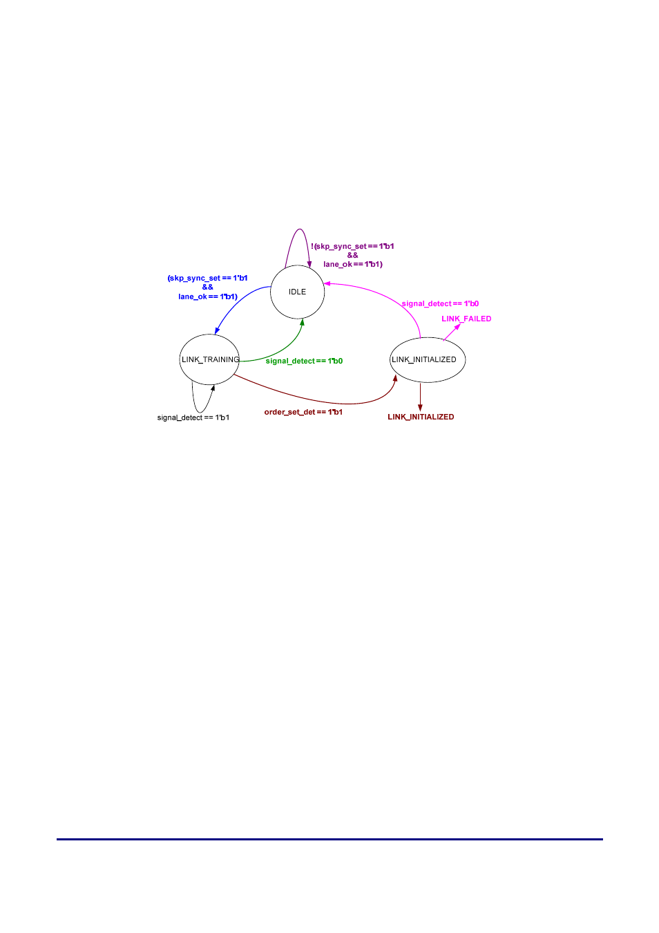
are OR’ed together to create a signal called “lane_ok”
The FSM diagram for Link_FSM is shown below in Figure 3.
Figure 3 – Link_FSM block state diagrams
In this state machine, the LINK_INITIALIZED state will ensure that both ends of the link are
properly initialized.
•
During link training, IDLE (//I//) ordered set will be transmitted.
•
The receiver will constantly hunt for //I// ordered set.
•
The embedded PCS block will recognize the IDLE ordered set and automatically align to the
sync (//K//) and skip (//R//) characters.
•
Link initialization failure will be set if no IDLE is detected by the receiver.
•
The user will have the option to reinitialize link training in the event of link failure.
•
The IDLE ordered set will be transmitted continuously on the lane whenever the link is idle
i.e. no data is present for transmission.
•
The Sync (//K//) character is used for comma-detection by the receiver. It maps to K28.5.
•
Skip (//R//) character is used for rate matching between the receiver and transmitter. The skip
character maps to K28.0.
•
The receiver must flag to the far-end device that it has detected and locked on to the IDLE
ordered sequence. This can be achieved by sending the sequence ordered set once the initial
10 µsecs counter inside LaneLinx has expired.
•
The sequence ordered set is - Sync (//K//) K28.5 and Skip (//R//) K28.0 always transmitted first
and after initialized then the D10.2 will be transmitted.
•
The sequence ordered set will be recognized by the LaneLinx state machine.
•
After the LINK_INITIALIZED signal gets asserted, then this block send the 16-bit parallel
data to the “rx_data_module” block.