Refer to, Section 3.4.2 – Cabletron Systems 6H129-08 User Manual
Page 34
Chapter 3: Installation
3-8
6H128-08 and 6H129-08 User’s Guide
c.
Make sure that the fiber connection meets dB loss specifications
for a 100BASE-FX link as specified in the Cabletron Systems
Cabling Guide.
d.
for information on how to manage the connected
port.
If a link has not been established, refer to
, before contacting the
Cabletron Systems Global Call Center. Refer to
problem has not been resolved.
3.4.2
Connecting a Twisted Pair Segment to the
FE-100TX
An FE-100TX installed in port 7 and/or 8 has an internal crossover
switch, which acts like a crossover cable. A schematic of a crossover
cable is shown in
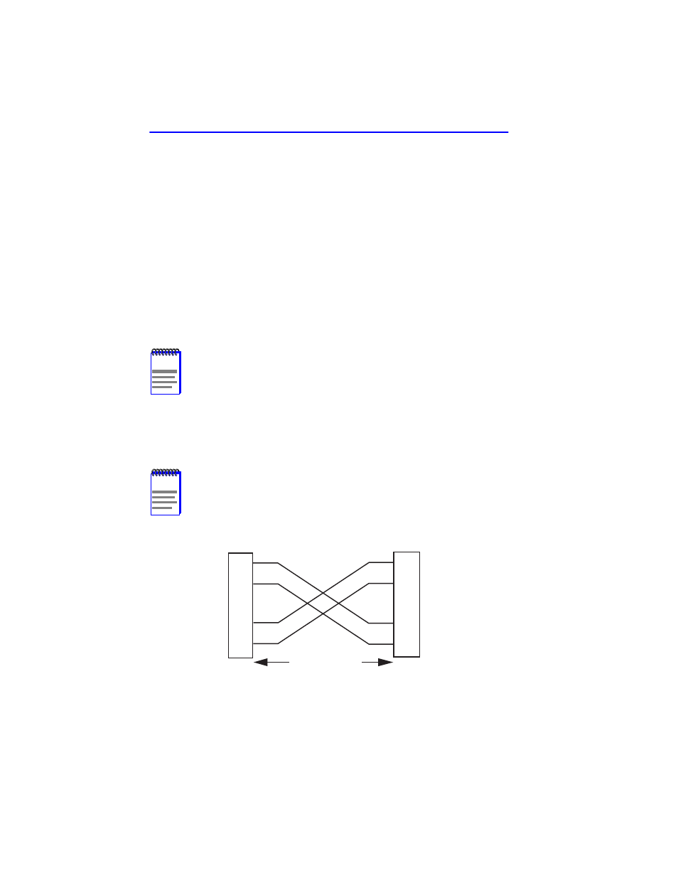
Figure 3-3
Cable Pinouts - (RJ45) Crossover Cable
NOTE
To ensure proper operation, use only Category 5 Unshielded
Twisted Pair (UTP) cabling that has an impedance of 85 to
111 ohms.
NOTE
RX+/RX- and TX+/TX- must share a common color pair. For
example, the receive pair may use the white/blue, blue/white
pair, while the transmit pair may use the white/orange,
orange/white pair.
TX+
TX–
RX+
RX–
2
1
3
6
10BASE-T Device Port
TX+
TX–
2
1
3
6
SmartSwitch RJ45 Port
2159_04
RJ45 to RJ45
RX+
RX–