Craftsman 113.24181 User Manual
Page 5
Attention! The text in this document has been recognized automatically. To view the original document, you can use the "Original mode".
the
supply
circuit)
or
when
the
supply
circuit
is
extremely
long.
Always
check
connections,
load
and
supply
circuit
when
the
motor
fails
to
perform
satisfactorily.
Check
wire
sizes
and
lengths
with
the
table in the next paragraph. Replace or repair damaged
or worn cord immediately.
CONNECTING TO POWER SOURCE OUTLET
This saw must be grounded while in use to protect the
operator from electrical shock.
If power cord is worn or cut, or damaged in any way, have
it replaced immediately.
CAUTION; This saw is wired for operation on 240 volts
only. Connect to a 15 ampere branch circuit protected by a
15 ampere time delay or circuit saver fuse or circuit
breaker.
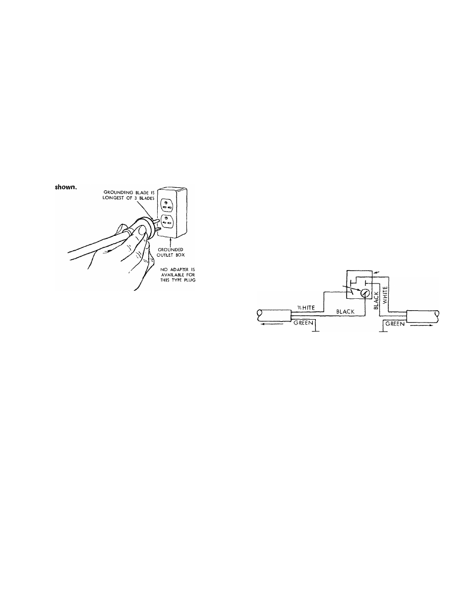
WARNING; Do not permit fingers to contact the terminals
of power or motor plugs when installing or removing the
plug to or from a live power source. Hold the plug as
WARNING;
IF
NOT
PROPERLY
GROUNDED
THIS
POWER
TOOL
CAN
INCUR
THE
POTENTIAL
HAZARD
OF
ELECTRICAL
SHOCK,
PARTICULARLY
WHEN
USED
IN
DAMP
LOCATIONS,
IN
PROXIMITY
TO
PLUMBING,
OR
OUT
OF
DOORS.
IF
AN
ELECTRICAL
SHOCK
OCCURS
THERE
IS
THE
POTENTIAL
OF
A
S E C O N D A R Y
HAZARD
SUCH
AS
YOUR
HANDS
CONTACTING THE SAWBLADE.
This power tool is equipped with a 3-conductor cord and
grounding type plug which has a grounding prong, approved
by
Underwriters'
Laboratories
and
the
Canadian
Standards
Association. The ground conductor has a green lug and is
attached to the tool housing at one end and to the ground
prong in the attachment plug at the other end.
The use of any extension cord will cause some loss of
power.
To
keep
this
to
a
minimum
and
to
prevent
over-heating
and
motor
burn-out,
use
the
table
below
to
determine
the
minimum
wire
size
(A.W.G.)
extension
cord.
Use
only
3
wire
extension
cords
which
have
3
prong
grounding type lugs and 3-pole receptacles which accept the
tools plug.
Extension Cord Length
Wire Size A.W.G.
Up to 100 ft.......................................................................... 14
100
ft. to
200
ft..................................................................
12
200 ft. to 400 ft.......................................................................
8
NOTE; For circuits of greater length, the wire size must be
increased proportionately in order to deliver ample voltage
to the saw motor.
- SV/ITCH
CAP INSULATOR
IF
YOU
ARE
NOT
SURE
THAT
YOUR
OUTLET
IS
PROPERLY
GROUNDED.
HAVE
IT
CHECKED
BY
A
QUALIFIED ELECTRICIAN.
WARNING;
DO
NOT
PERMIT
FINGERS
TO
TOUCH
THE
TERMINALS
OF
PLUGS
WHEN
INSTALLING
OR
REMOVING THE PLUG TO OR FROM THE OUTLET.
TO MOTOR
TO PLUG
GROUND
GROUND
CONTENTS
WARRANTY ................................................................................................. 2
GENERAL SAFETY INSTRUCTIONS
FOR POWER TOOLS ...............................................................................2
ADDITIONAL SAFETY INSTRUCTIONS
FOR TABLE SAWS...................................................................................3
MOTOR SPECIFICATIONS AND ELECTRICAL
REQUIREMENTS ..................................................................................... 4
UNPACKING AND CHECKING CONTENTS .............................................
Tools Needed............................................................................................
6
List of Loose Parts...................................... •.........................................
6
Attaching Legs........................................................................................ 7
Checking Table Insert .............................................................................7
Checking Blade Squareness to Table ..................................................
8
Attaching Table Extension .....................................................................
8
Installing Rip Fence Guide Bars.............................................................9
Aligning Rip Fence ................................................................................ 11
Adjusting Rip Scale Pointer................................................................. 12
Installing Blade Guard ......................................................................... 12
GETTING TO KNOW YOUR SAW ............................................................. 14
On-Off Switch ......................................................................................... 14
Elevation Crank .................................................................................... 15
Elevation Lock ...................................................................................... 15
Tilt Crank ................................................................................................ 15
Rip Fence ............................................................................................... 15
Miter Gauge ............................................................................................. 15
Blade Guard............................................................................................. 15
Table Insert .............................................................................................. 15
Removing and Installing Saw
Blade ......................................... 16
Exacti-Cut .............................................................................................. 16
BASIC SAW OPERATION USING THE MITER GAUGE 17
Work Helpers.......................................................................................... 17
Crosscutting........................................................................................... 18
Repetitive Cutting ................................................................................. 18
Miter Cutting .......................................................................................... 19
Bevel Crosscutting ............................................................................... 19
Compound Miter Cutting....................................................................... 19
BASIC SAW OPERATION USING THE RIP FENCE . . 20
R ipping ................................................................................................... 20
Bevel Ripping ......................................................................................... 20
Resawing ................................................................................................ 22
Cutting Panels ........................................................................................ 22
Rabbeting ............................................................................................... 22
M iter Gauge ............................................................................................23
Heeling Adjustment or Parallelism of
Sawblade to Miter Gauge Groove....................................................... 23
Blade Tilt, or Squareness of
Blade to Table .................................................................................... 24
Elevation Lock .........................................................................................26
RECOMMENDED ACCESSORIES............................................................
REPAIR PARTS ............................................................................................ 30