Craftsman 137.248850 User Manual
Page 15
Attention! The text in this document has been recognized automatically. To view the original document, you can use the "Original mode".
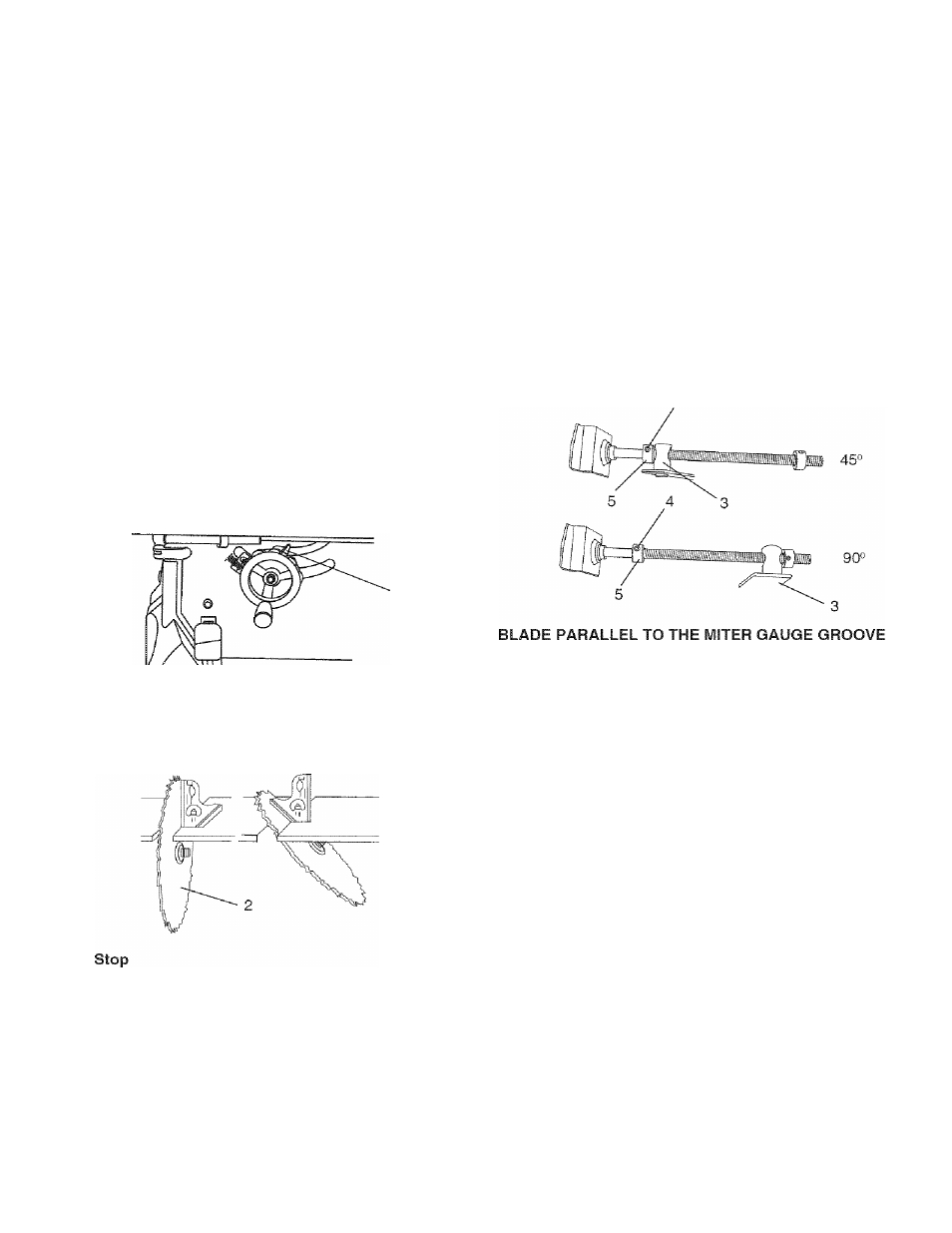
90“ (0“) Stop
1. Disconnect the saw from the power source.
2. Turn the blade elevation handwheel and raise the
blade to the maximum elevation.
3. Loosen the blade bevel lock knob (1) and move the
blade to the maximum vertical position, then tighten
the lock knob (1).
4. Place a combination square on the table and against
the blade (2) to determine if the blade is 90° (0°) to
the table. (Fig. P)
5. ft the blade is not 90° (0°) to the table, loosen the two
set screws (4), located on the collar (5) underneath
the table saw (Fig. Q) with the hex key (Carton
Contents J) and back off the collar.
6. Loosen the bevel lock knob, turn the blade tilting
handwheel to move the blade until it is 90° (0°) to the
table and tighten the bevel lock knob.
7. Adjust the collar (5) so it contacts the bracket (3)
when the blade is 90° (0°) to the table. Tighten the
two set screws (4) (Fig. Q).
Fig. O
Fig. P
90®(0“)
45«
45°
1. With the blade in the upright 90° (0°) position, loosen
the bevel lock knob and move the blade to the
maximum bevel angle.
2. Place the combination square on the table as shown
in Fig. P to check if the blade is 45° to the table.
3. If the blade is not 45° to the table, loosen the two set
screws (4), located on the collar (5) underneath the
table saw, (Fig. Q) with the hex key (Carton Contents
J), and back off the collar.
4. Loosen the blade bevel lock knob, turn the blade
tilting handwheel to move the blade until it is 45° to
the table and tighten the blade bevel lock knob.
5. Adjust the collar (5) so it contacts the bracket (3)
when the blade is 45° to the table. Tighten the two
set screws.
BLADE TILTING POINTER
1. When the blade is positioned at 90° (0°), adjust the
blade tilt pointer to read 0° on the scale.
2. Loosen the mounting screw, position pointer over 0°
and tighten the screw.
NOTE: Make a trial cut on scrap wood before making
critical cuts. Measure for exactness.
Fig.Q
(FIG. R, S)
A WARNING
This adjustment was made at the factory, but it
should be rechecked and adjusted if necessary.
A
WARNING
To prevent personal injury:
• Always disconnect plug from the power source
when making any adjustments.
• This adjustment must be correct or accurate cuts
can not be made. Also inaccurate adjustment can
result in kickback and serious personal injury.
1. Remove the safety switch key and unplug the saw.
2. Remove the blade guard for this procedure but
reinstall and realign after adjustment.
3. Raise the blade to the highest position and set at the
0° angle (90° straight up).
4. Select and mark, with a felt tip maker, a blade tooth
having a “right set” and rotate the blade so the
marked tooth is LL in. above the table.
5. Place the combination square base (1) into the right
side miter gauge groove (2). (Fig. R)
6. Adjust the rule so it touches the front marked tooth
and lock ruler so it holds its position in the square
assembly.
15