Craftsman 137.248850 User Manual
Page 12
Attention! The text in this document has been recognized automatically. To view the original document, you can use the "Original mode".
2
.
3.
4.
5.
6
.
Raise the blade arbor (4-Fig. F) to the maximum
height by turning the blade raising handwheel
counterclockwise.
Place the open-end wrench (8) jaws on the fiats of
the saw arbor to keep the arbor from turning (Fig. G)
and place the box-end wrench (9) on the arbor nut
(5), and turn counterclockwise.
Remove the arbor nut (5) and outer flange (6-Fig. F).
install the saw blade onto the arbor with the BLADE
TEETH POINTING TOWARD THE FRONT OF THE
SAW.
install the flange (6) against the blade and thread the
arbor nut (5) as far as possible by hand. Ensure that
the blade is flush against the inner side of the blade
flange.
A WARNING
A
WARNING
To avoid possible injury and damage to the
workpiece, be sure to INSTALL THE BLADE WITH
THE TEETH POINTING TOWARD THE FRONT OF
TABLE in the direction of the rotation arrow on the
blade guard.
Fig. F
7. To tighten the arbor nut, (5) place the open-end
wrench (8) on the flats of the saw arbor to keep the
arbor from turning (Fig. G).
8. Place the box-end wrench (9) on the arbor nut (5),
and turn clockwise (to the rear of the saw table).
9. Replace the blade insert in the table recess, insert
the screws through the front and rear holes and
tighten remembering the rubber adjusting spacer
(4-Fig. E) under the rear of the insert and leveling the
rear of the insert to the table.
Fig. G
To avoid injury
from
a thrown workpiece, blade
parts, or blade contact, never operate saw without
the proper insert in place. Use the original installed
insert
for
all through-sawing operations except dado
cuts. A special dado insert plate must be installed
when using a dado blade.
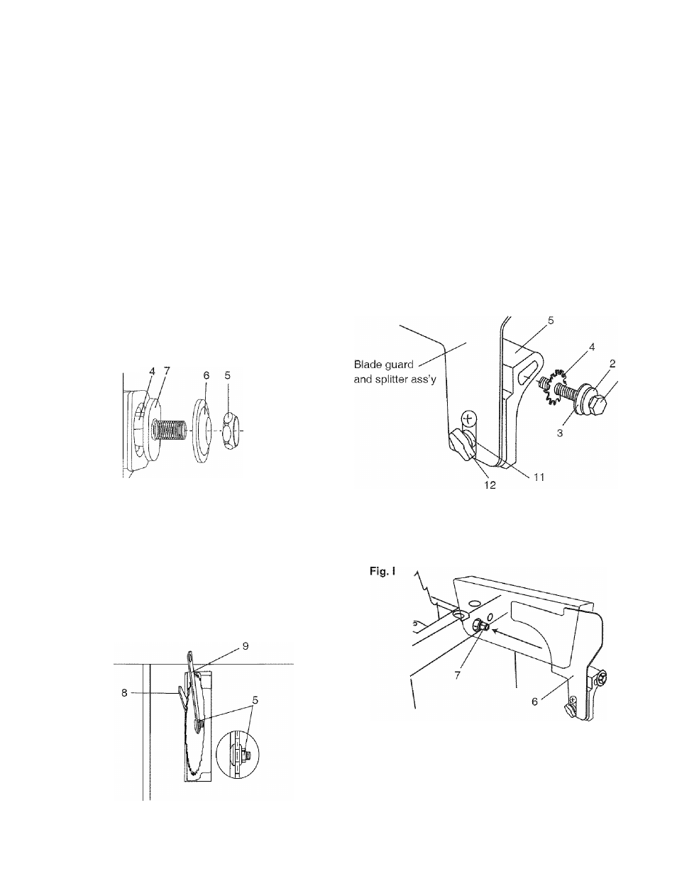
BLADE GUARD ASSEMBLY (FIG. H, I, J)
1. Set the blade to maximum height and the tilt to zero
degrees on the bevel scale with the hand wheels.
Lock the blade bevel lock knob.
2. Place the spring washer (2), flat washer (3), external
tooth lock washer (4) onto the blade guard mounting
bolt (1) (Fig. H).
3. insert bolt and washer assembly through splitter
bracket (5).
Fig. H
4. install the blade guard and splitter assembly (6) into
the rear of the saw table. Thread the bolt (1-Fig. H)
into the internally threaded pivot rod (7) until snug.
Lift blade guard arm (8) up and using a straight
edge, align the blade guard and splitter ass’y (9) with
the saw blade (10) (Fig. J).
Shift the splitter bracket assembly to right or left until
parallel alignment to the blade is achieved.
12