Craftsman 137.248850 User Manual
Page 11
Attention! The text in this document has been recognized automatically. To view the original document, you can use the "Original mode".
MOUNT SAW ON WORK SURFACE
1. if the stand will not be used, the saw must be
properly secured to a sturdy workbench using the
four mounting holes at the base of the saw.
2. Square the saw on the mounting surface and mark
the location of the four 3/8 in. mounting holes.
3. Drill the four 3/8 in. holes into the mounting surface.
4. Place the saw on the work surface, and align the
mounting holes of the saw with those drilled through
the surface.
5. Fasten the saw to the work surface. Using hardware
such as 1/2 in. lug bolts with washer.
A WARNING
Do not operate this machine on the floor. This is
very dangerous and may cause serious injury.
A WARNING
Always keep your work area clean, uncluttered and
well lit.
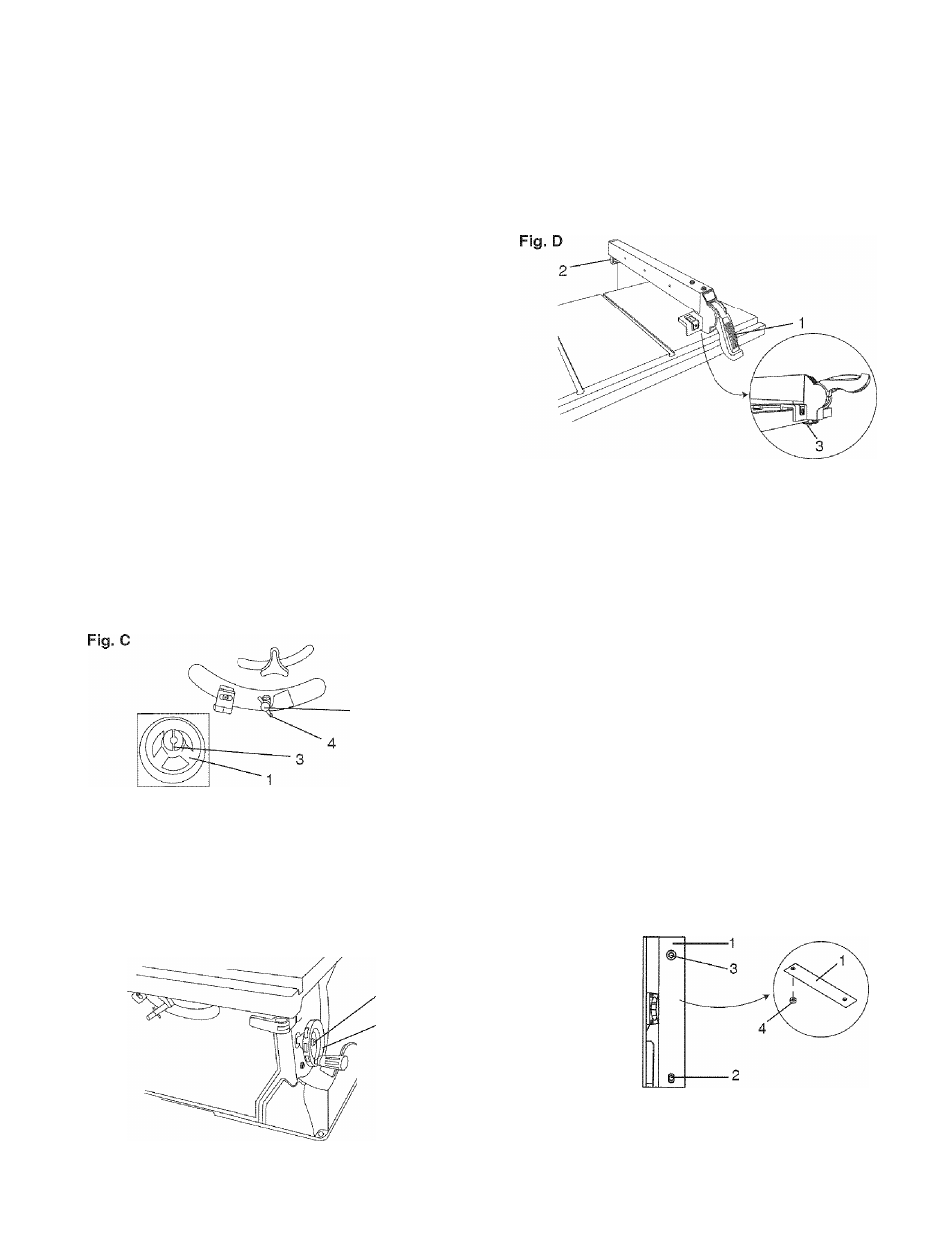
BLADE RAISING HANDWHEEL (FIG. C)
1. Attach the up ~ down handwheel (1) to the elevation
rod (2) at the front of the saw. Make sure the slots (3)
in the hub of the handwheel (1) engage with the pins
(4).
2. Attach and tighten the dome nut (5 - Fig. C-1).
BLADE TILTING HANDWHEEL (FIG. C-1)
1. Attach the bevel 0° ~ 45° handwheel (6) to the blade
tilting rod on the right side of the saw in the same
manner as above.
2. Attach and tighten the handwheel dome nut (5).
RIP FENCE (FIG. D)
1. Lift upward on the rip fence handle (1) so the rear
holding clamp (2) is fully extended.
Place the rip fence on the saw table, and attach the
set plate (3) under the fence handle (1) to the rail
first.
Push down on the fence handle (1) to lock.
2
.
INSTALLING AND CHANGING THE BLADE
(FIG. E, F, G)
A
WARNING
• To avoid injury from an accidental start, make
sure the switch is in the OFF position and the
plug is not connected to the power source outlet.
• To avoid serious injury, the rear of the table insert
must be level with the table. To adjust rear of
table insert, adjust the screw (3) in or out until
the rear of the insert is level to or slightly above
the table. To raise the insert, turn the screw
counterclockwise, to lower the insert, turn the
screw clockwise. NOTE: A rubber adjusting
spacer (4) is provided under rear of insert for this
purpose.
1. Remove the table insert (1) by removing the two
screws (2, 3). Be careful not to lose the rubber
adjusting spacer (4) that is on the back screw (3)
beneath the table insert (Fig. E).
Fig. E
Fig. C-1
11