Craftsman 137.248850 User Manual
Page 14
Attention! The text in this document has been recognized automatically. To view the original document, you can use the "Original mode".
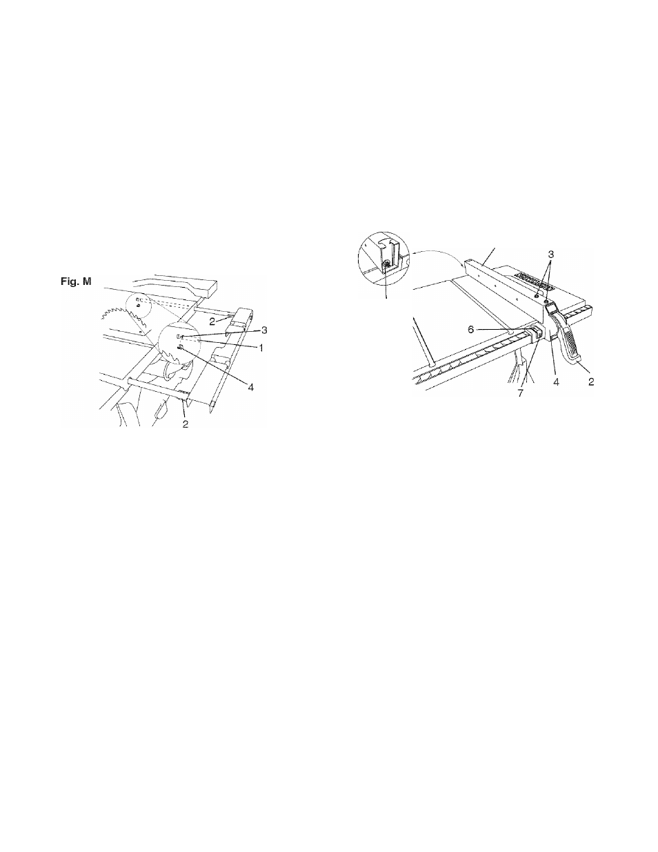
INSTALLING REAR TABLE EXTENSION (FIG. M)
1. Place the rear table extension onto the two rear table
extension tubes (1).
2. Snap two long location seats (2) over the two rear
table extension tubes (1). Make sure the locating pin
in the location seat fits into the matching hole (3) in
the extension tube.
3. Insert rear table extension tubes (1) into the two
holes in the rear of the saw table and into extension
tube brackets under the table. Position rear table
support so instruction labels are facing up.
4. Snap one short location seat (4) over the end of the
left rear table extension tubes (1). Make sure the
locating pin in the location seat fits into the
matching hole in the extension tube.
ADJUSTING REAR TABLE EXTENSION
1. Rear table extension should be positioned as close
as possible to the rear of the table when ripping short
work pieces.
2. Rear table extension should be pulled out fully until
the location seat prevents It from moving outward
when ripping long work pieces that require extra
support as you are completing the cut.
5. If fence is loose when the handle is In the locked
(downward) position, do the following;
• Move the handle (2) upward and turn the adjusting
nut (5) clockwise until the rear clamp is snug.
• Over-tightening the adjusting screw will cause the
fence to come out of alignment.
A WARNING
Failure to properly align fence can cause “kickback”
and serious injury.
Fig.N
RIP FENCE INDICATOR ADJUSTMENT (FIG. N)
1. The rip fence indicator (6) points to the measurement
scale. The scale shows the distance from the side of
the fence to nearest side of the blade.
2. Measure the actual distance with a rule, ft there
is a difference between the measurement and the
indicator, adjust the indicator (6).
3. Loosen the screw (7) and slide the indicator to the
correct measurement on the scale. Tighten the screw
and remeasure with the rule.
RIP FENCE ADJUSTMENT (FIG. N)
1. The fence (1) is moved by lifting up on the handle (2)
and sliding the fence to the desired location. Pushing
down on the handle locks the fence in position.
2. Position the fence on the right side of the table and
along the edge miter gauge groove.
3. Lock the fence handle. The fence should be parallel
with the miter gauge groove.
4. If adjustment is needed to make the fence parallel to
the groove, do the following;
• Loosen the two screws (3) and lift up on the
handle (2).
• Hold the fence bracket (4) firmly against the front
of the saw table. Move the fence until it is parallel
with the miter gauge groove.
• Push the handle down and tighten both screws.
A WARNING
To avoid injury from an accidental start, make sure
the switch is in the OFF position and the plug is not
connected to the power source outlet.
ADJUSTING THE 90° (0°) AND 45° POSITIVE STOPS
(FIG. O, P, Q)
Your saw has positive stops that will quickly position the
saw blade at 90° (0°) to the table. Make adjustments
only if necessary.
14