Two Brothers Racing Yamaha Rhino User Manual
V.a.l.e, Rhino 700, 5 “ 1” or less
V.A.L.E.
V a r i a b l e a x i s l o c k i n g e x h a u s t
TM
IMPORTANT - PLEASE READ CAREFULLY
We recommend that this performance part be installed by a qualified motorcycle technician.
If you have any doubts as to your ability to install this performance part, please consult with
your local motorcycle dealer. Read all instructions first before starting installation. Make sure
the motorcycle and exhaust system are completely cool before starting the installation. Also,
make sure the bike is secure on a centerstand or ideally a service lift during installation. Be
sure to save all stock components for possible use later.
Installation Instructions
NOTE: Instructions continued on Page 2...
Parts List
2008 Yamaha
RHINO 700
V.A.L.E.™ Complete DUAL Exhaust System with M-7 Canisters
Part # 005-2170106D
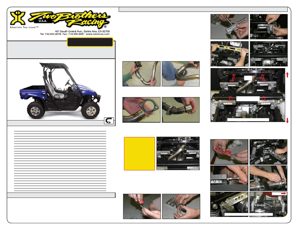
Slide rubber clamp liner inside the 4 muffler clamps.
Carefully slide rubber lined clamps over the muffler and
loosely secure to mounting brackets. Use threadlock, lock
washers and large OD washers. Leave loose for now.
9.
10.
Make sure the ATV is completely cool before starting
the installation. Make sure the ATV is secure and the
wheels are choked to prevent rolling during installation.
Remove the bed from the rear section of the Rhino.
First remove the pins in the hinges, unhook the
hydraulic shocks, then disconnect the electronics.
Remove the heat shield from the top of the motor.
Remove the stock headpipe and remove the mounting
bolts hardware and brackets holding the stock muffler.
You will need to twist and rotate the stock muffler
assembly in order to remove it from the chassis.
Connect both left and right header and slip tubes, join
together with the 80mm springs.
Slide the flange over the header tube with the part number
edge going on first. Then slide the collar over the end of the
exhaust tube that will connect to the cylinder head.
Install the new TBR head pipes making sure that the OEM
sealing gasket is between header collar and cylinder head.
Use the supplied 8mm lock nuts to secure header flange to
cylinder head. Leave loose for now.
Install mounting brackets to frame as shown. The rear
brackets have a radius for bed hydrolic shock clearance.
Use threadlock and lock washers on all hardwarre. Make
sure brackets are level with each other. Because of the
differences with every Rhino, this bracket may fit tighter on
some frame rails due to paint and/or heat from production
welds and twisting. This is normal.
1.
2.
3.
4.
5.
6.
7.
8.
IMPORTANT:
The
driver’s
side
header system has less
bend when compared
to the passenger side.
Both exhaust will go
under the drive shaft.
Install the passenger
side first. The driver’s
side goes in front of the
passenger side.
Rear brackets have radial bends.
Front
Fr
o
n
t
R
ea
r
5 “
1” or Less
Bracket Spacing Measurements
1
2
3
4
5
6
Qty.
Description
Part Number
1
Left Muffler Canister M-7
005-217-206ML
1
Right Muffler Canister M-7
005-217-206MR
1
Left Header
005-21701H-L
1
Right Header
005-21701H-R
4
Heavy Duty Muffler Clamp
005-2C4
1
HARDWARE KIT
005-217-4
4
X-Ring (half)
005-7-2-3
2
Header Collar
005-152-17-2
2
Steel Header Flange
005-152-15S-2
4
80mm Spring
005-S-80
2
Billet Bolt-on Muffler Mount (Front)
005-217-21
2
Billet Bolt-on Muffler Mount (Back w/ radius)
005-217-21B
4
Billet Bolt-on Muffler Mount “U” Brackets
005-217-21U
8
8x40mm Socket Head Cap Screws
005-SH840
12
M8 Split High Collar Lock Washers
005-WL8
8
M6 Split High Collar Washers
005-WL6
4
8x1.25mm Pitch Metal Locking Flange Nuts
005-FNL8
4
8mm Large Flat Washers
005-WO8
4
8x20mm Socket Head Cap Screws
005-SH820
2
Spark Arrester Screen (Installed)
005-106S
8
6x14mm Socket Head Cap Screws
005-SH614
1
5mm Long Handle Ball end hex key
005-9-18610
1
Permatex High Strength Threadlock
031-P09179
1
TBR Sticker Kit
015-10212