Taylor-Wharton 24K w/ AutoTend User Manual
Page 9
Main Control
The “brain” for the control system “talks” to the interface unit and makes all
decisions regarding liquid levels, temperatures, valve opening/closing, etc. It is
either housed in a separate box, or located away from the Interface Panel.
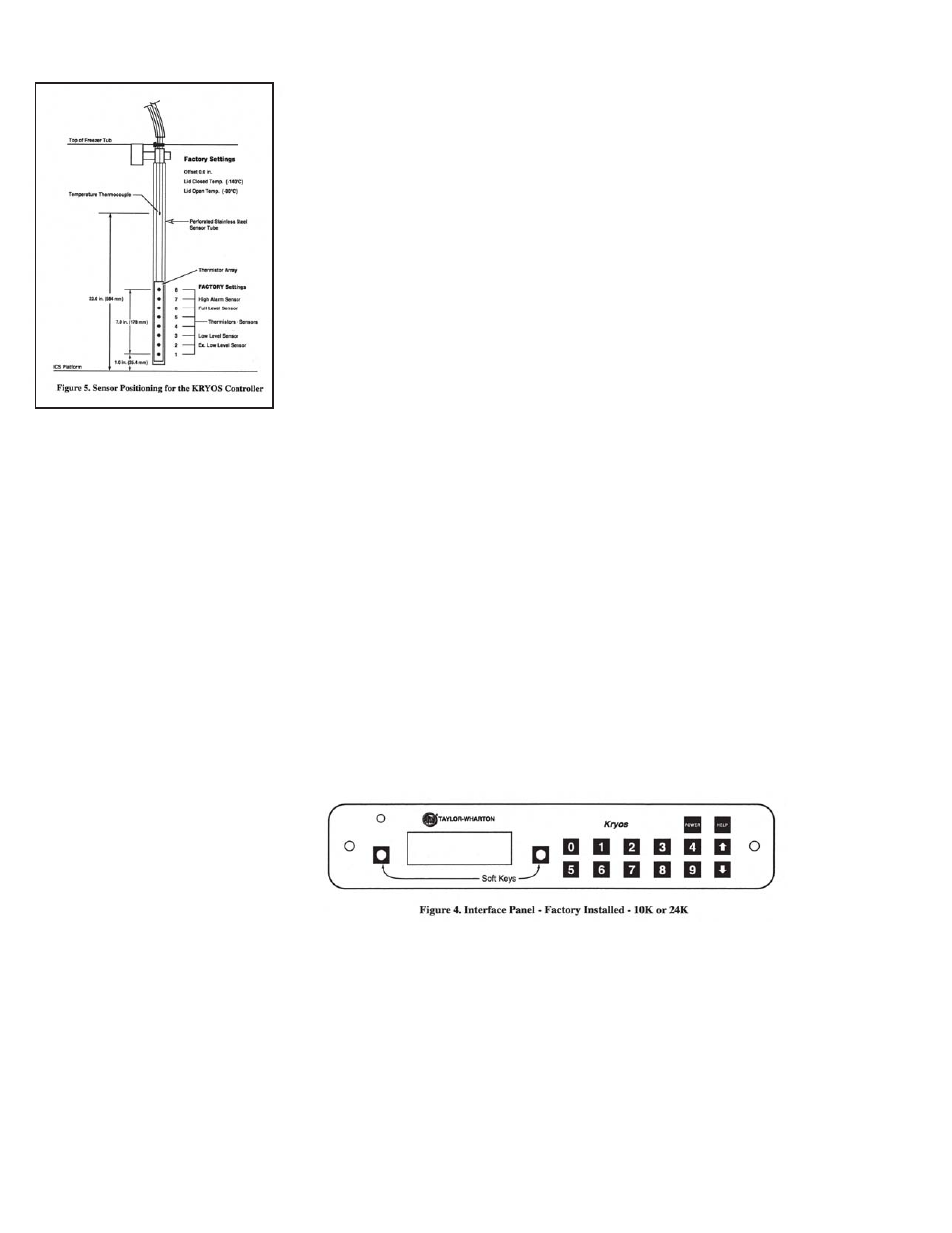
Sensor Assembly
A standard 7+1 thermistor assembly, includes the Freeze-Guard over-fill sensor.
Optional 4 thermistor, or 8 thermistor sensor assembly can be ordered. The 4
thermistor assembly maintains the liquid level between 2 middle sensors. The 8
thermistor assembly maintains the liquid level between the high sensor and the
low sensor assigned by the user. The standard 7 thermistor assembly is similar to
an 8 sensor assembly in that the user can select the START FILL and STOP FILL
positions. The eighth position on this assembly is tied into an inline plumbing
thermistor, which detects if the solenoid valve fails to close.
Lid Switch
Is attached to the hinge and determines whether or not the lid is open on the
freezer. This also allows the control to determine whether to active the Quickchill
or Auto Defog features.
Solenoid Valve
Is designed to work with 24 VAC solenoid valves manufactured by Valcor, Parker-
Hannifin, ASCO or Alcon.
Thermocouples
Type T thermocouples determine the temperature in the freezer. The user may
choose to use NONE, 1 or 2 thermocouples with this control at any time.
Wall Transformer
A 24 VAC, 40 VA wall transformer is required. The system is supplied with a trans-
former compatible with common household (North American) 110VAC. These wall
transformers have UL approval. UL approval for the system as a whole is not required
since the control operates on such a low voltage. If your power source differs, or is
subject to disruption or line surges due to other equipment on line, consult your
Taylor-Wharton representative.
Remote Alarm
If an error condition occurs for a user defined period of time a remote alarm circuit
can be initiated. This is accomplished by connecting a remote device to the remote
alarm jack on the rear electrical panel. The 3-pin jack on the back of the unit provides
continuity between pin #2 (common) and pin #1 in the normal condition. Continuity
between pin #2 and pin #3 is provided in an error condition (See Figure 6).