Replacing the processor module – Dell XPS M2010 (MXP061, Mid 2006) User Manual
Page 57
Processor Module: Dell XPS M2010 Service Manual
file:///C|/Users/santhosh_v.ASIA-PACIFIC/Desktop/Hawke/New%20folder/cpu.htm[2/21/2014 11:26:24 AM]
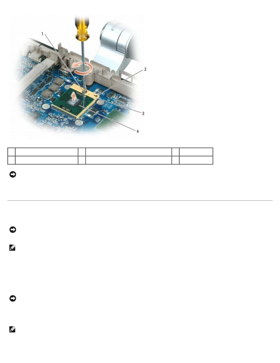
1 ZIF-socket cam screw
2 pin-1 corner of microprocessor
3 ZIF-socket
4 processor module
NOTICE:
When removing the processor module, pull the module straight up. Be careful not to bend the pins on the
processor module.
9. Lift the processor module from the ZIF socket.
Replacing the Processor Module
NOTICE:
Ensure that the cam lock is in the fully open position before seating the processor module. Seating the
processor module properly in the ZIF socket does not require force. A processor module that is not properly seated can
result in an intermittent connection or permanent damage to the processor and ZIF socket.
NOTE:
The pin-1 corner of the processor module has a triangle that aligns with the triangle on the pin-1 corner of the
ZIF socket.
1. Align the pin-1 corner of the processor module with the pin-1 corner of the ZIF socket, and place the processor module
on the socket.
When the processor module is correctly seated, all four corners are aligned at the same height. If one or more corners
of the module are higher than the others, the module is not seated correctly.
NOTICE:
To avoid damage to the processor, hold the screwdriver so that it is perpendicular to the processor when
turning the cam screw.
2. Tighten the ZIF socket by turning the cam screw clockwise to secure the processor module to the system board.
NOTE:
When you replace the processor thermal-cooling assembly, be sure to place a new thermal pad on the
processor thermal-cooling assembly.