System board components, Figure 14 – Dell OptiPlex GX110 User Manual
Page 26
3. Free the power supply from the securing tab labeled "RELEASE
—>, " and rotate it upward until it locks in its extended position.
System Power Supply Removal
To remove the system power supply, perform the following steps:
1.
Rotate the system power supply
2. Disconnect the power cables from all drives.
3. Remove the power supply cables from the system board.
4. Lift the front of the power supply until it stops. Then rotate the power supply away from the chassis.
5. Lift the power supply out of the chassis.
System Power Supply Installation
To reinstall the system power supply, align the swivel points at the rear of the power supply with the holes in the chassis and power supply support
arm. Then perform the
in reverse.
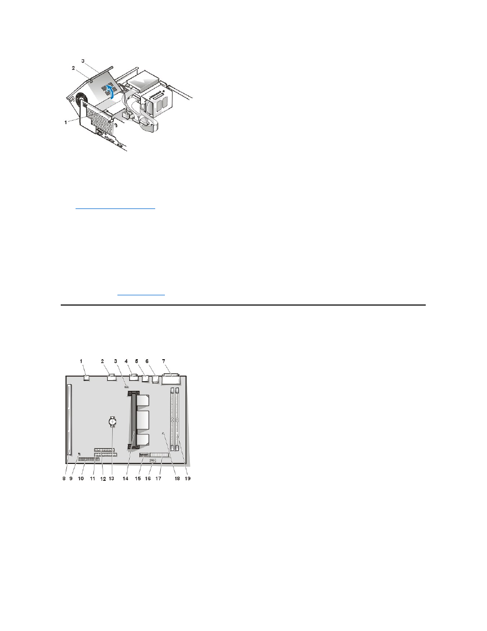
System Board Components
Figure 14 shows the system board and the location of all its sockets and connectors.
Figure 14. System Board Components
1 Securing tab
2 Power supply
3 Release latch
1 NIC connector
2 Video connector
3 Fan power connector
4 Serial port 2 connector
5 USB connectors (2)
6 Mouse (upper) and keyboard (lower) connectors
7 Parallel port (upper) and serial port 1 (lower)
connectors
8 Riser board connector
9 System board jumpers
10 IDE1 connector
11 IDE2 connector
12 Diskette/tape-drive connector
13 Battery
14 Microprocessor
15 3.3-V power connector
16 Control panel connector
17 DC power connector
18 Auxiliary power indicator
19 DIMM connectors (2)