Serial connector, Parallel connector – Dell PowerEdge 1500SC User Manual
Page 5
l
COM2, COM4: IRQ3 (shared setting)
These COM ports have the following I/O address settings:
l
COM1: 3F8h
l
COM2: 2F8h
l
COM3: 3E8h
l
COM4: 2E8h
For example, if you add an internal modem card with a port configured as COM1, the system then sees logical COM1 as the address on the modem card. It
automatically remaps the integrated serial connector that was designated as COM1 to COM3, which shares the COM1 IRQ setting. (Note that when you have
two COM ports sharing an IRQ setting, you can use either port as necessary but you may not be able to use them both at the same time.) If you install one or
more expansion cards with serial connectors designated as COM1 and COM3, the corresponding integrated serial connector is disabled.
Before adding a card that remaps the COM ports, check the documentation that accompanied your software to make sure that the software can be mapped to
the new COM port designation.
To avoid autoconfiguration, you may be able to reset jumpers on the expansion card so that the card's port designation changes to the next available COM
number, leaving the designation for the integrated connector as is. Alternatively, you can disable the integrated connectors through the System Setup
program. The documentation for your expansion card should provide the card's default I/O address and allowable IRQ settings. It should also provide
instructions for readdressing the connector and changing the IRQ setting, if necessary.
If you add an expansion card containing, for example a parallel connector configured as LPT1 (IRQ7, I/O address 378h), you must go into the System Setup
program to remap the integrated parallel connector.
For general information on how your operating system handles serial and parallel ports, and for more detailed command procedures, see your operating
system documentation.
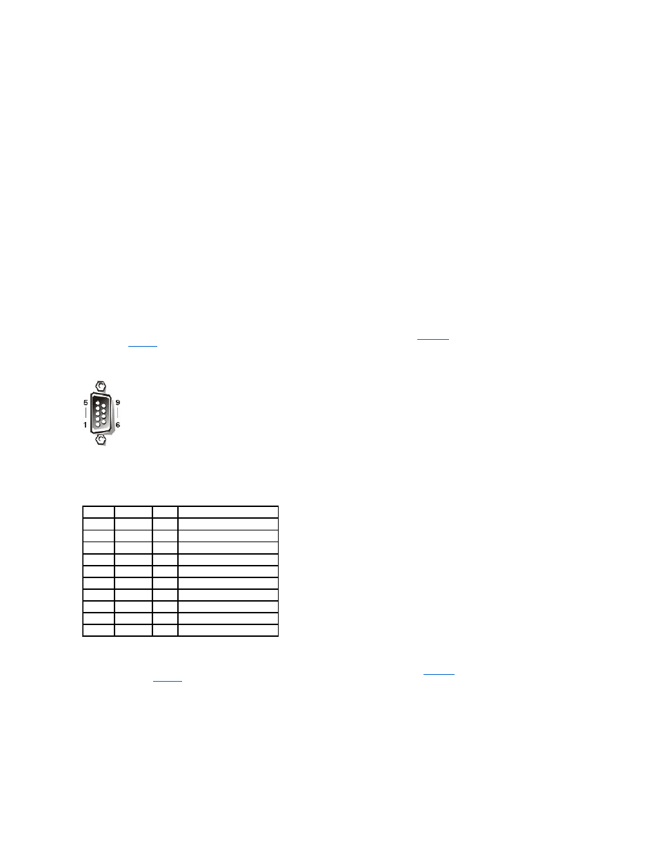
Serial Connector
illustrates the pin numbers for the serial
defines the pin assignments and interface signals for the serial connector.
Figure B-2. Serial Connector Pin Numbers
Parallel Connector
If you reconfigure your hardware, you may need pin number and signal information for the parallel connector.
illustrates the pin numbers for the
parallel connector and
defines the pin assignments and interface signals for the parallel connector.
Figure B-3. Parallel Connector Pin Numbers
Table B-1. Serial Connector Pin Assignments
Pin
Signal
I/O
Definition
1
DCD
I
Data carrier detect
2
SIN
I
Serial input
3
SOUT
O
Serial output
4
DTR
O
Data terminal ready
5
GND
N/A
Signal ground
6
DSR
I
Data set ready
7
RTS
O
Request to send
8
CTS
I
Clear to send
9
RI
I
Ring indicator
Shell
N/A
N/A
Chassis ground