Dell OptiPlex GX200 User Manual
Page 52
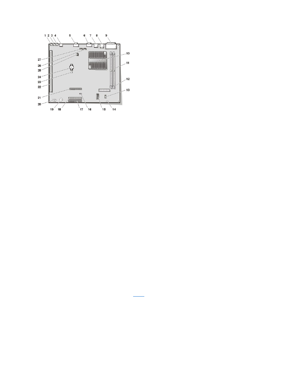
System Board Jumpers
Figure 25 shows the location of the jumpers on the system board.
lists the system board jumpers and their settings.
Figure 25. System Board Jumpers
1 Line-in connector
2 Line-out connector
3 Microphone connector
4 NIC connector
5 Video connector
6 Serial port 2 connector
7 USB connectors (2)
8 Keyboard (lower) and mouse (upper) connectors
9 Parallel port (upper) and serial port 1 (lower) connectors
10 Microprocessor connector
11 RIMM sockets (2)
12 DC power 1 connector
13 DC power 2 connector
14 Chassis intrusion connector
15 Control panel connector
16 External speaker connector
17 EIDE1 connector
18 EIDE2 connector
19 System board speaker
20 System board jumpers
21 Diskette/tape-drive connector
22 Riser board connector
23 Real-time clock reset (RTCRST) jumper
24 Battery
25 Modem audio connector
26 Fan connector
27 CD audio cable connector
- Inspiron 530 (2 pages)
- OptiPlex 755 (82 pages)
- OptiPlex 755 (45 pages)
- OptiPlex 755 (248 pages)
- OptiPlex 755 (622 pages)
- OptiPlex 755 (528 pages)
- OptiPlex 760 (76 pages)
- OptiPlex 760 (203 pages)
- OptiPlex 745 (212 pages)
- OptiPlex 745 (360 pages)
- OptiPlex 745 (428 pages)
- OptiPlex 780 (73 pages)
- OptiPlex 780 (40 pages)
- OptiPlex 780 (14 pages)
- OptiPlex 780 (89 pages)
- OptiPlex 780 (10 pages)
- OptiPlex 780 (74 pages)
- OptiPlex 780 (80 pages)
- OptiPlex GX620 (221 pages)
- OptiPlex GX620 (294 pages)
- OptiPlex GX620 (338 pages)
- Inspiron 530 (226 pages)
- OptiPlex 960 (Late 2008) (16 pages)
- OptiPlex GX260 (100 pages)
- OptiPlex GX260 (235 pages)
- OptiPlex FX160 (Late 2008) (132 pages)
- OptiPlex FX160 (20 pages)
- OptiPlex FX160 (Late 2008) (20 pages)
- OptiPlex 210L (258 pages)
- OptiPlex 210L (150 pages)
- OptiPlex 210L (130 pages)
- OptiPlex 210L (128 pages)
- OptiPlex 210L (300 pages)
- OptiPlex 320 (140 pages)
- OptiPlex 320 (132 pages)
- OptiPlex 320 (312 pages)
- OptiPlex 320 (266 pages)
- OptiPlex 320 (356 pages)
- OptiPlex 320 (44 pages)
- OptiPlex GX240 (86 pages)
- OptiPlex GX240 (283 pages)
- OptiPlex GX240 (298 pages)
- OptiPlex GX240 (182 pages)
- OptiPlex GX240 (144 pages)
- OptiPlex GX240 (121 pages)