Led indicators and buttons – Cisco 10008 User Manual
Page 5
5
Cisco 10008 Router Performance Routing Engine 3 Installation
OL-8544-01
Product Overview
Figure 2
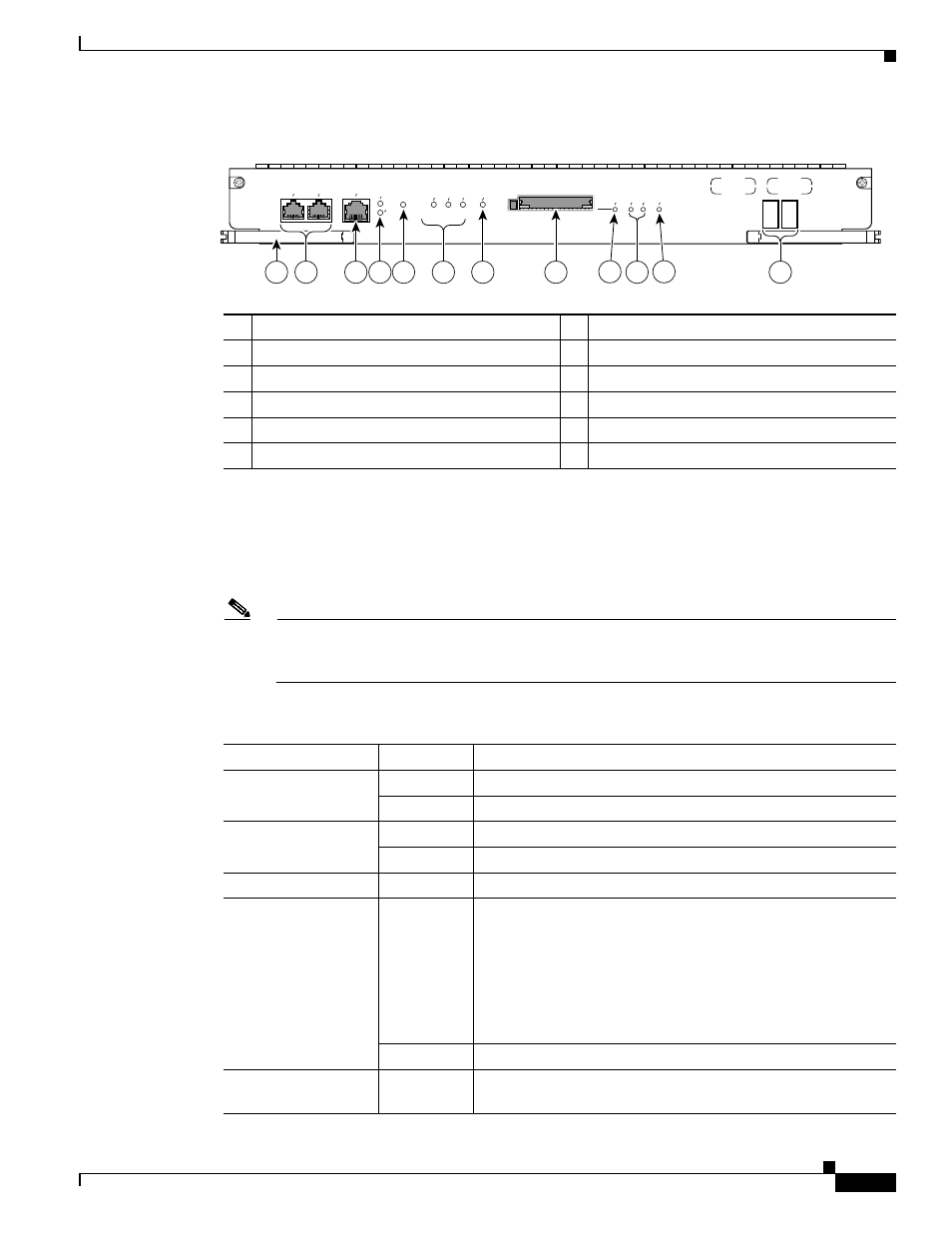
PRE3 Front Panel
LED Indicators and Buttons
LEDs on the front panel of the PRE3 provide a visual indication showing the status of PRE3 operation.
describes the PRE3 LEDs and buttons. Use
to understand the LEDs and
buttons.
Note
F or additional information about alarm connections, see the Cisco 10000 Series Router
Performance Routing Engine Installation, at the following URL:
1
Ejector Levers
7
ACO (Alarm Cut-off Button)
2
Console and Auxiliary Ports
8
CompactFlash Slot, Disk0
3
Network Management Ethernet (NME) Port
9
Slot0 (Disk0) LED
4
Activity and Link LEDs
10 Status, Fail LEDs
5
Push-button reset
11 BITS LED
6
Alarms: Critical, Major, Minor
12 Alphanumeric Display
149536
PERFORMANCE ROUTING ENGINE
ALARMS
CISCO
10000
ACTIVITY
LINK
CRITICAL
MAJO
R
MINO
R
AC
O
SLO
T 0
ST
ATUS
FAIL
BITS
ETHERNET
AU
X
CONSOLE
P/N
ESR-PRE3
1
3
7
8
9
2
10
6
12
11
5
4
Table 1
PRE3 LED Status and Button Descriptions
LEDs and Button
Status
Description
ACTIVITY
Green
Packets are being transmitted and received.
Off
No activity.
LINK
Green
Carrier detected, the port is able to pass traffic.
Off
No carrier detected, the port is not able to pass traffic.
Push-button reset
n/a
Resets the PRE3.
CRITICAL, MAJOR,
and MINOR LEDs
Off
No alarm.
Note
Alarm relay contacts can be used to connect the router
to an external visual or audio alarm system. This feature
enables any CRITICAL, MAJOR, or MINOR alarms
generated by the router to activate the visual or audible
alarms. Shutting off an audible alarm does not disable
the alarm LEDs.
Yellow
Indicates an alarm condition.
ACO (Alarm cut–off)
button
n/a
Pressing this button disables an audible alarm.