Usb connectors, Integrated nic connectors, Table b – Dell PowerEdge 6650 User Manual
Page 7
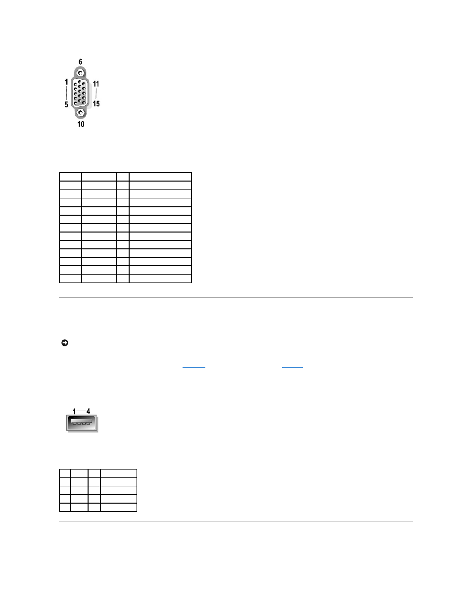
USB Connectors
Your system contains a single USB connector on the front control panel, and two USB connectors on the rear panel for attaching USB-compliant devices.
The following is pin information for the USB connectors.
illustrates the USB connector and
defines the pin assignments and interface
signals for the USB connector.
Figure B-6. PIN Numbers for the USB Connector
Integrated NIC Connectors
Your system has two integrated 10/100/1000–Mbps NICs. The 10/100/1000-Mbps NIC provide communication between servers and workstations and efficient
Table B-4. Video Connector Pin Assignments
Pin
Signal
I/O Definition
1
RED
O
Red video
2
GREEN
O
Green video
3
BLUE
O
Blue video
4
NC
N/A No connection
5–8, 10 GND
N/A Signal ground
9
VCC
N/A VCC
11
NC
N/A No connection
12
DDC data out O
Monitor detect data
13
HSYNC
O
Horizontal synchronization
14
VSYNC
O
Vertical synchronization
15
DDC clock out
O
Monitor detect clock
Shell
N/A
N/A Chassis ground
NOTICE:
Do not attach a USB device or a combination of USB devices that draw a maximum current over 500 mA per channel or +5 V. Attaching devices
that exceed this threshold may cause the USB ports to shut down. See the documentation that accompanied the USB devices for their maximum current
ratings.
Table B-5. USB Connector PIN
Assignments
Pin Signal I/O Definition
1
Vcc
N/A Supply voltage
2
DATA- I/O Data
3
DATA+ I/O Data
4
GND
N/A Signal ground