Video connector, Table b, Mouse connector – Dell PowerEdge 6650 User Manual
Page 6
.
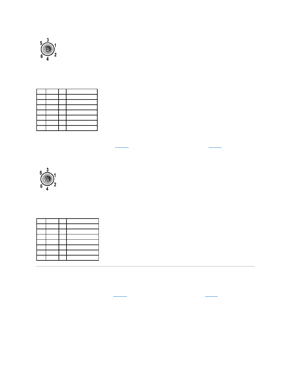
Mouse Connector
The following is pin information for the mouse connector.
and illustrates the pin numbers for the mouse connector.
assignments and interface signals for the mouse connector.
Figure B-4. Pin Numbers for the Mouse Connector
Video Connector
The system uses a 15-pin high-density D-subminiature connector on the front and back panels for attaching a VGA-compatible monitor to your system. The
video circuitry on the system board synchronizes the signals that drive the red, green, and blue electron guns in the monitor.
The following is pin information for the video connector.
illustrates the pin numbers for the video connector, and
defines the pin
assignments and interface signals for the video connector.
Figure B-5. Pin Numbers for the Video Connector
Table B-2. Keyboard Connector Pin
Assignments
Pin
Signal
I/O Definition
1
KBDATA I/O Keyboard data
2
NC
N/A No connection
3
GND
N/A Signal ground
4
FVcc
N/A Fused supply voltage
5
KBCLK
I/O Keyboard clock
6
NC
N/A No connection
Shell N/A
N/A Chassis ground
Table B-3. Mouse Connector Pin
Assignments (Back Panel)
Pin
Signal
I/O Definition
1
MSDATA I/O Mouse data
2
NC
N/A No connection
3
GND
N/A Signal ground
4
FVcc
N/A Fused supply voltage
5
MSCLK
I/O Mouse clock
6
NC
N/A No connection
Shell N/A
N/A Chassis ground