Processor thermal-cooling assembly – Dell Latitude D830 (Early 2007) User Manual
Page 15
Back to Contents Page
Processor Thermal-Cooling Assembly
Dell™ Latitude™ D830 Service Manual
1.
Follow the procedures in
Before You Begin
.
2.
Remove the hinge cover (see
Hinge Cover
).
3.
Remove the keyboard (see
Keyboard
).
4.
Remove the display assembly (see
Display Assembly
).
5.
Remove the palm rest (see
Palm Rest
).
6.
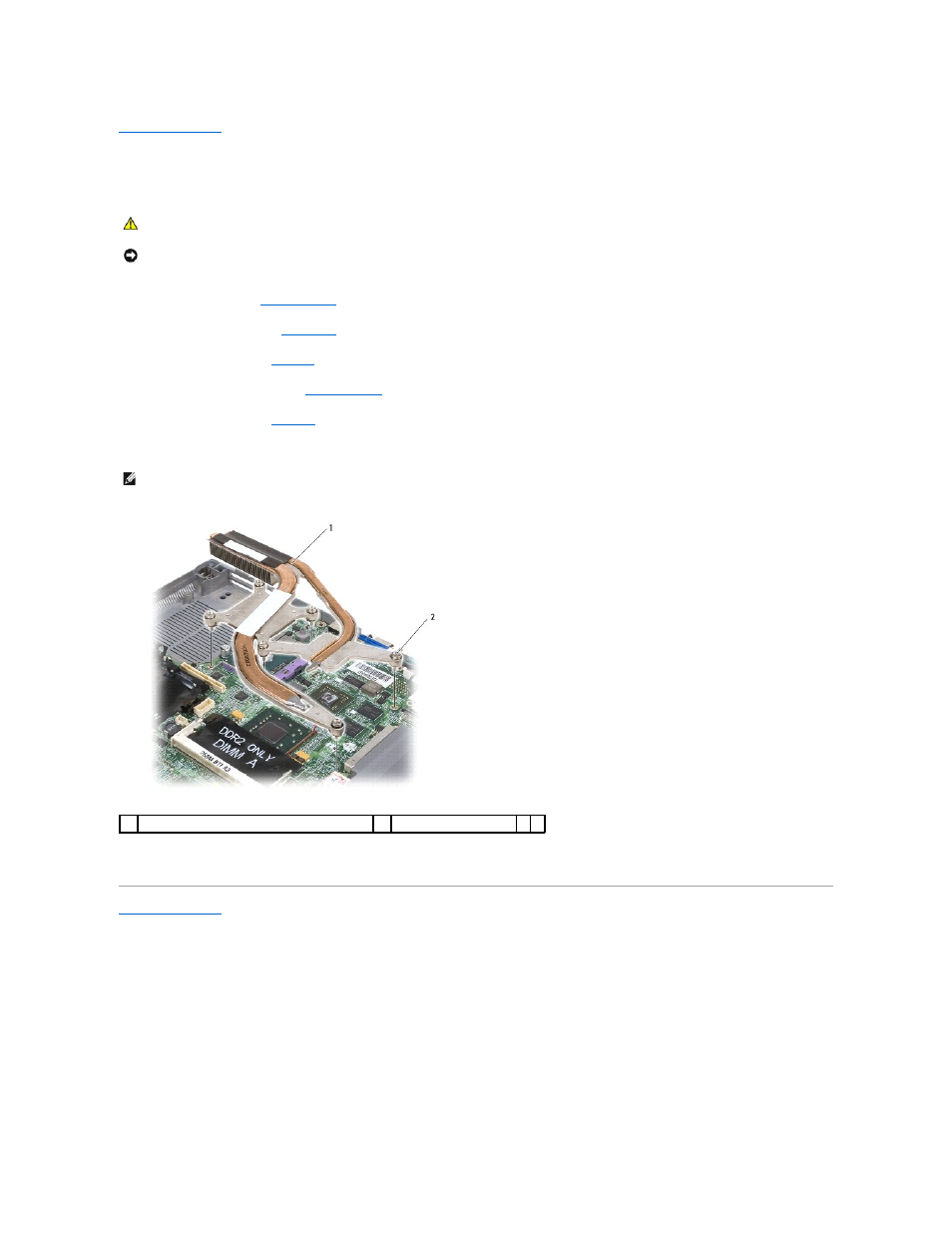
Loosen in consecutive order the six captive screws, labeled "1" through "6" that secure the processor thermal-cooling assembly.
7.
Lift the assembly out of the computer.
Back to Contents Page
CAUTION:
Before performing the following procedures, follow the safety instructions in the Product Information Guide.
NOTICE:
To avoid electrostatic discharge, ground yourself by using a wrist grounding strap or by periodically touching a connector on the back
panel of the computer.
NOTE:
The appearance of the thermal-cooling assembly for system boards with integrated graphics varies from that for system boards with discrete
graphics (shown). The thermal-cooling assembly for discrete graphics (shown) has six captive screws to loosen versus five captive screws for the
integrated graphics solution.
1
processor thermal-cooling assembly
2
captive screws (6)